Jeep Enthusiast Forums banner

Explorer 8.8 Axle Teardown/Rebuild/Install

70K views 153 replies 35 participants last post by  Feetwet  
#1 ·
Here is the link to make the pictures work, for Chrome and Firefox.
https://www.jeepforum.com/forum/f17...com/forum/f176/photobucket-fix-chrome-firefox-4181513/?hotlinkfix=1511972149450

I have no issues with my stock D35. I run it hard hunting and fishing and it doesn't complain ( I must have one of the "good" ones :laugh:), but when I came across this 8.8, I couldn't pass it up. From a 98 Explorer.


These are rare around these parts . Even harder to find Axle Code 42 which is 4:10 gears and Open Diff. I've been on the lookout for months and when my local Auto Salvage notified me they had found one, I snatched it up. 300 bucks out the door.

Ominous shape in my garage door...


Knocked together a set of rolling cradles and dropped it in.


Toby, my Supervisor, approves...


The plan will be to clean this thing up, strip off all the brackets and brake hardware, pull the carrier and pinion, install all new bearings and seals and run a new brake system. In other words, a complete rebuild.
 
#2 ·
Now let's see what we got.

Passenger brake system


Differential section


Driver brake section


Brake line routing over diff


Pass Parking Brake connection


Driver Parking brake connection


After a degreasing and power wash it's looking a little better.
Partial teardown. Swaybar and brake lines gone. Rusty cover removed.


The Goods. After 2 cans of Brake Cleaner,surprisingly good shape. Teeth show no appreciable wear, old gear oil was black but no shavings or silver particles. I'm encouraged...


I ran an initial pattern check to see what ballpark I was in...

Drive side, favoring the heel but well centered and well within spec.


Pinion flange had some in and out play and ZERO preload. Pinion bearings are failing but that's okay...they're outta here anyway.
 
#140 ·
hey feetwet, I know ths may seem like a weird question but currently I am working on my 8.8 and once opening the diff cover i noticed that everything was black and i could scrape it off with my finger nail. Was this similar to you? Did you power wash the inside of your diff and axle housings? not really sure how to go about cleaning everything without taking it apart.

thanks,
Phil
 
#3 ·
A couple taps with a BFH popped the rotors loose.

Parking Brakes are shot, as expected.


At this point I had pulled the axles, carrier and pinion. No need to go into great detail, it's the same basic procedure. Pull the center pin bolt and center pin, slide axles in a bit and pull the C clips and slide the axles out. Just take care to mark orientation on your bearing caps and shims for carrier bearings, they are side specfic, of course.

Some quick notes, though. Carrier Bearing Cap Bolts are 3/4" Hex. No Case Spreader needed. Center Pin Bolt is 5/16" Hex.
Pinion nut is 1 1/16", breaker bar probably needed to get it loose. I put a Drift Pin through a Flange Bolt hole and against the housing to keep the flange from turning during removal.
I used a 3 jaw puller to remove the Pinion Flange, hold onto the pinion when this comes loose, the pinion will want to drop out.
Pull Pinion Seal, then the outer bearing and Oil Shield will be loose in the housing.

Now to get after those axle bearings and seals.

A $5 seal puller is the tool for this. A couple whacks with the BFH and out they come.


Now you want one of these. $30 at Harbor Freight.


This one will do nicely...


Back off the nut, insert "T" toggle end in behind bearing and lock down the nut and washer.


Attach slide hammer, couple of firm jolts and...


thar she blows...


Repeat for other side. Now it's time to take a wire wheel on an angle grinder and get after all that rust. I also pulled a rag soaked in Brake cleaner through the tubes a couple times. Felt like I was swabbin out a Howitzer :laugh:.

I decided to go with a High Temp Epoxy Paint on this job, along with some serious Adhesion Promoter. Should hold up okay.


Wire wheel, Brake cleaner, Prime and Paint.


Now you want one of these. Seal Driver Kit. Also $30 at Harbor Freight. These drivers make this job a breeze.


Here are the new Bearings and Seals with matching Drivers.


Prelube bearings with your goop of choice.


Ready to install.


Cleaned up the tube ends.


Bearing started then tapped in.


Bearing seated.


A little High Temp RTV and new seal.


A little dab'll do ya...The RTV I used is the same color as the Bearing grease. Don't get em wrong...


Tapped in and done.


Next up, the new Parking brakes.
 
#12 ·
snip

Prelube bearings with your goop of choice.


A little High Temp RTV and new seal.

snip

Very nice writeup and pictures! :cheers2:

I'm curious about the RTV on the outside of the seal. Did you see some instructions that it was necessary or was it just preventative?

Also, why was it necessary to prelube the bearings? Shouldn't the oil flow from the pumpkin to the tube/bearing after you fill it up with gear oil?

Thanks!
 
#4 ·
Backing plates look a little better now. Went with shoes and hardware from NAPA. No need to get crazy, they're just E Brakes.
Shoes Napa P/N UP-10701-PB
Hardware Kit NAPA P/N 2979

Some White Lithium Grease on the raised bosses where the shoes ride...


All 4 shoes are identical. Pick 2. Attach large inner top spring. Hold thusly.


Insert tops of shoes into actuator lever and spread bottoms apart.


Insert newly lubed and assembled adjuster wheel.


Use a clamp or your third hand and hold shoe back against backing plate. Insert pin from rear and through hold-down clip. twist pin to secure.


Attach large top outer spring and small lower spring. I'll adjust them later.


Over to the grinding table.


One done.


Plenty of meat left on these rotors. they"ll go back on.


All cleaned up.


Some paint on the hats.


Also did the axles and diff housing while I had it all going on...


Next up...bearings and seals in the differential housing.:thumbsup:
 
#5 ·
The Carrier Bearings are in perfect shape. After a thorough degreasing and inspection I elected to leave them alone. The Pinion Bearings are another story.
With all the play in the Pinion Flange, and no Pinion Bearing Preload, these need to be swapped out.

Pinion Bearing Inner Napa P/N M802048
Pinion Bearing Cup Inner Napa P/N M802011
Pinion Bearing/Cup Outer NAPA P/N BR52
Pinion Seal NAPA P/N 18136

Using a Drift pin, tap out the Pinion Cups (Races). Access to the edges can be had through the oil galleys.


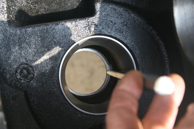
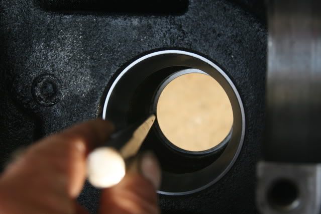
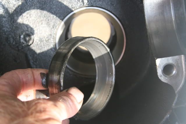
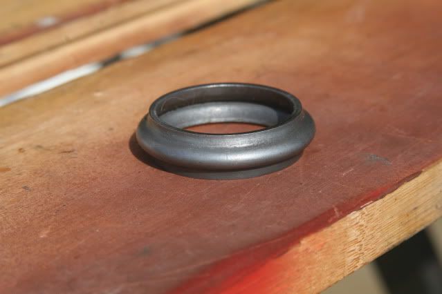
This is what you're after.


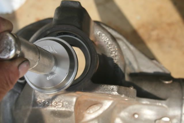
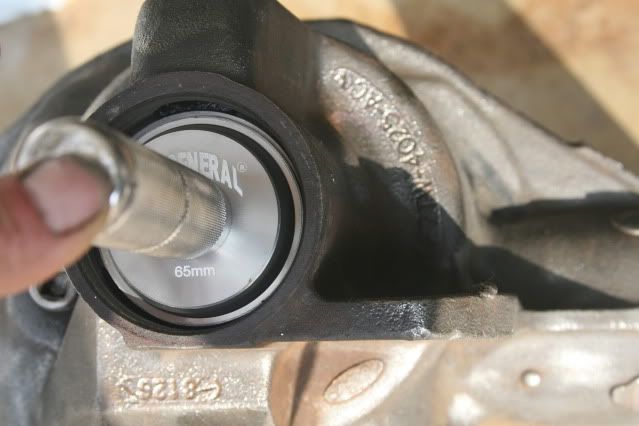
Clean surfaces, lightly oil cup seat and edges of new cup and drive to seat using 81mm Drive on Inner and 65mm for outer.


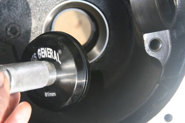
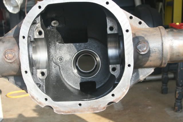
Races (cups) completed, ready for Pinion install.


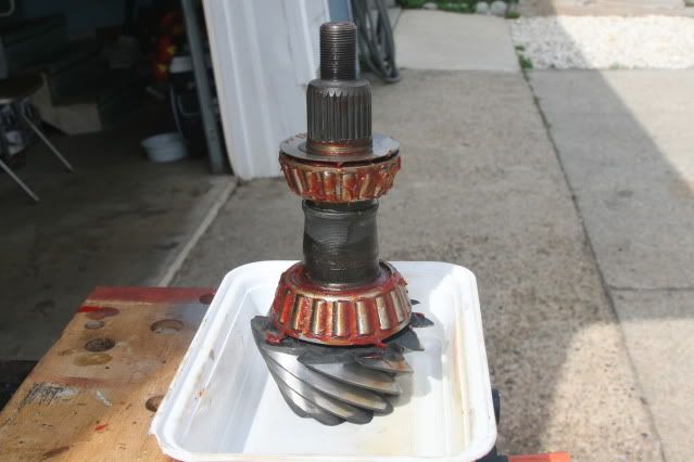
I used a friend's Shop Press to swap inner bearings. No mystery here...press off, press on. There was a factory shim between the pinion gear head and the bearing. This was cleaned up and reused. Prelubed and ready to go in.

From the top down...Oil Shield, Outer Bearing (both loose and slid on for visuals), small gap where Crush Sleeve will live, Inner Bearing, Shim and Pinion Gear Head.


Crush Sleeve was Dealer Item P/N B7A-4662-A Spacer-Pinion


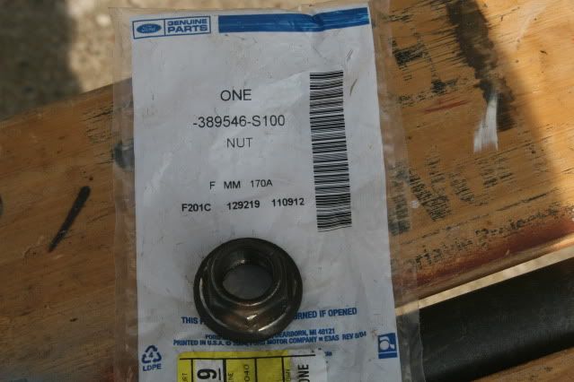
Pinion Nut was Dealer Item P/N 389546-S100 Nut-Flanged


Here's the part that is really easy. The only problem was both hands full of grease so I wasn't touching the camera...:nono:
I rotated the axle to pinion up in the cradle. Placed the Outer Pinion Bearing in the race with the oil shield on top. Next a bead of RTV and tap in the Pinion Seal. Also run a light bead of RTV around the splines in the Pinion Flange, about halfway up the shaft.
Slide the Crush Sleeve onto the Pinion Shaft and slide the assembly up into the housing from below. It'll pick up the Outer Bearing and Shield as it comes through the back of the housing.

Tap the Flange Yolk into place while holding the Pinion up and start the nut. Now it's hangin there lookin nifty. :thumbsup:

It should be noted at this point that I used the old nut with a little oil under the cap to reduce friction. I will crush the sleeve most of the way with this one, then remove it, clean the area and replace with the new one for final setup. The new nut comes preloaded with Threadlocker.

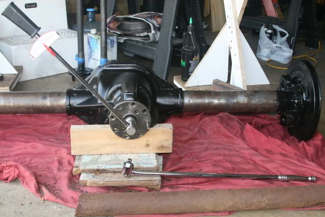
Cranking down on the Crush Sleeve can be a chore with the axle out of the vehicle. It wants to flip all over the place. I set it on the ground and had a beefy neighbor hold down one end. You can see a drift pin through the flange bolt hole at the 3 o'clock position to keep the flange from rotating.
1 1/16" Hex socket, 3ft Breaker Bar and a 5ft section of Big Rusty Pipe (henceforth known as the BRP). Worked just fine.
Began cranking the Pinion Nut tight using a regular 1/2" ratchet. Jumped to the Breaker Bar, then added the BRP.


As the nut tightens, periodically check the Flange for resistance to rotation. You did beg, borrow or steal an inch/pound Beam-style Torque Wrench, Right? :cool:
Now it's an 1/8th of a turn and check preload. 1/8th of a turn and check preload.
You're looking for 8-14 in/lbs of resistance on used gears and 16-29 in/lbs for new gears. It may take a little more pressure to start the rotation but read your Beam Torque Wrench while rotation is underway...

When I got close I backed off the old nut, cleaned up the area and installed the new one, then tightened to my final values. If you overdo it here you're getting a new Crush Sleeve and starting all over, so be patient.
I settled for 22 in/lbs of Pinion Bearing Preload. Used gears but new bearings. Should be good to go.

Time to drop the Carrier back in. Fully degreased and Bearings prelubed. I lightly painted the pinion and carrier Gear Teeth with 75-90w Gear Oil to get a smooth mesh. Races held in place with shims on their proper sides, drop that puppy into place. Place Bearing caps in their proper orientation and lightly tap em to seat. Clean Cap Bolts, add Threadlocker and Torque to 75ft/lbs.


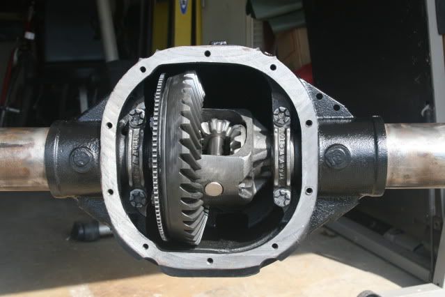
Time to see how I did.
Harbor Freight once again for a Dial Indicator and Magnetic Base. ($14 & $12 resp.)
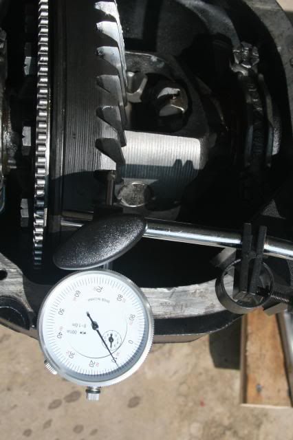
Set up 90* to a Ring Gear Tooth and Set Dial to Zero. Hold Pinion and rotate Ring Gear til it engages the Pinion. You're looking for a value of .010, the amount of "play" in the Ring gear before it wants to move the Pinion.

Zeroed out


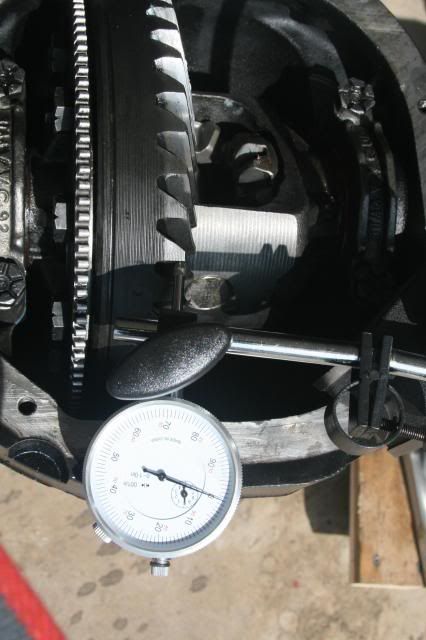
.010 Backlash on the money!


Now to check the Pattern. White Lithium Grease for Marking Compound.

Fingers crossed...

Drive


Coast


New Pinion Bearings and correct Pinion Bearing Preload has brought the drive side down to the center of the tooth with diffuse edges. Nice contact. Most excellent.
Coast is a tad high but well within spec.

Moving on....!:cheers2:
 
#6 ·
Time to put the axles back in. Simple. First, check the inboard ends for a rubber O ring. Both mine were split.


Replacements from the hardware store. A roll in some gear oil and pop em on.


I'm guessing they add a little pressure to the C clip and keep them tight in there.

If you reassembled the carrier after you got the axles out, like I did, it's time to remove the Center Pin Bolt. 5/16" socket will do.


Slide Center Pin out.( yeah, it's an earlier picture...)


Oil up the rubber on your axle seals and carefully slide the axles in, supporting the weight as you go. Almost in, give a gentle twist to engage the splines and slide them home.

Now the ends poke into the area vacated by the Center Pin. Slide the C clips into the channels over the O rings.


C clips loaded.


Now pull the axles outboard and insert the Center Pin. Locktite on the Center Pin Bolt and snug er up tight. 8ft/lbs or something, just get it tight.


Adjust the Parking Brakes now, piece of cake. Throw a rotor on and see how much slop there is between shoe and rotor. Mine had a lot. Pull the rotor off, slide a pin under the spring to release the adjuster wheel and start cranking.
The spring lays in the curve of the adjuster wheel and keeps it from spinning.
There is an access port on the backside of the backing plate but the adjuster is hard to reach from there.
Fine tune the adjustment from there later if you have to. Doable, just awkward.


On and off with the rotor and keep adjusting out til it just barely contacts the shoe.


Pop the rotors back on and call it good.

Time to weld those tubes.
There are 3 plug welds at the diff on each tube. While okay for every day use, if you're gonna beat on your rig you want to add some insurance. Wheel hop coupled with high RPMs has been known to shear the welds and spin a tube now and again. Not that my little 4 banger will be putting out massive torque :p, but a little insurance won't hurt.

I chose to do three stitch welds on each tube, located between the factory plug welds, as opposed to a full perimeter weld. I was a bit concerned about the high heat possibly warping the tubes. Maybe overly cautious but I'm comfortable with this approach.

The Supervisor is looking forward to this...


Hurry up and wait for the Auto Darken Batt to Solar charge...


The Setup.


I didn't want to overthink this stage too much. I've heard so many differing opinions about welding to cast, high nickle rod, low hydrogen, etc. I'm just gonna dive in and see how it goes.

The Prep. Preheated area with propane torch for a few minutes.


The stitch w/6013 rod.


Slag cleaned up.


Ground smooth. ( mostly)


Painted up.


Carried that around both tubes, alternating and allowing for cool down. I think it will be fine.

Chased the Flange Yolk threads with a 12mm x 1.75 tap to clean em out.


So that's where it stands for the moment. New Diff cover, Lubelocker gasket, Flange Yolk Adapter, Perches, U bolt Kit all enroute from various suppliers and due any time now.

Meanwhile, I'll pick up the Disc Brake lines, hoses, Calipers and Pads and get the Brake job underway.

I'll post up my progress as I make some...:laugh:
 
#11 ·
Thanks for the kind words guys.

There were a couple of posts lately from guys asking about what to do now that they found their 8.8.
I figured I'd take the pics as I went along and post em up.
Lotsa fun to do, hope this helps people down the road.

:cheers2:
 
#13 ·
Hey Stan.
Thanks for reading. I know you have an 8.8 Axle as well.

I prelube bearings as a general rule. The more grease the better.

In this case it may be a little while til I'm ready to fill the Diff with gear oil. Loading up the bearings will keep em happy as I spin the axles or pinion for various reasons as the build progresses. Still have to mock up my perches and set the Pinion angle, yank it back out and weld and so on.
After the gear oil is added then yes, all those components will be swimming.

As to the RTV, I always want sealant on metal to metal contact where seals are mounted. The press-in fit is probably good enough, but now I'm sure...:thumbsup:
 
#14 ·
Nice write up, nice work.:thumbsup:

It appears at some point you've already cut off the old perch's. Did you take measurements prior? It could be helpful/easier for the new perch location.


WRM
 
#16 ·
Nice write up, nice work.:thumbsup:

It appears at some point you've already cut off the old perch's. Did you take measurements prior? It could be helpful/easier for the new perch location.
WRM
Thanks WRM.
Not a lot to cutting off the brackets and others have covered it so I kinda blew past that in the writeup...

As for measurements, I pulled centers from the shoulders of the diff housing on each side where the tubes enter. Made a snazzy drawing and everything...:laugh:
I'll locate the perches from there and cover that in the writeup at that point.

Thanks for picking up on that..
 
#15 ·
Good writeup.

I welded the whole tubes. I needed to rent a 220v welder, all I have is a 110 wire welder(not good enough for tubes), and it was $$ to rent($60 for the morning), so I welded the whole thing. With nickel rods. Bought more rods than needed so I used them up...)Preheated it with a torch too. Used my wire welder for the rest of the welding.
 
#17 ·
I had plenty of buzzbox, no worry there. Penetration on the stitches looked okay but I'm no pro.
I'll keep an eye on em, see if they show any cracking down the road...so to speak... :p
 
#19 ·
The Axle build progresses. Picked up the parts for the brake job.

Got the new OEM calipers painted up. No need to go high end on these, they'll be just fine. I'm partial to the Blue Engine Enamel for the brakes.


Got the Spicer 1330 Flange Yolk and painted that up. Taped off the bearing cups though...


OEM Brake hoses spec'ed for the 98 Exploder, Pass and Driver side.
These will be switched side for side upon install. You'll see why...


The caliper install tools.


Went with the High End shoes, Good, Better, Best type deal.

Here's how you load them.
Inner shoe goes in first. It has a 3 prong back, full notch and Wear Indicator Clip at the bottom.


Press it all the way in.


Now the outer, full notch at bottom again. Just clip it on.


The metal sleeve inside the rubber boot may need to be slid back toward the outside. May be a snug fit, even with the factory lube.


these notches need to be at the bottom.


Set the aforementioned notches onto the lower arm of the bracket.


Then roll the caliper forward til it rests against the upper arm..


A liberal dose of Antisieze on the caliper bolts, align the holes and crank em home. Torque to 7-15ftlbs.


Should look like this when you're through. Bleeder at the TOP if you please.... :cool:


#20 ·
Next up, the kind folks at RuffStuff sent along a Care package. Item # 88SS-31 Rear Axle Swap 31 Spline.

I knew it was a popular kit but I wasn't ready for the BEEF of these things.


The perches are made for both 3 1/8" and 3 1/4" axles. As I have the 8.8 @ 3 1/4", I had to grind these nubs off the two perches for a perfect fit.


You could hang a whole Jeep off these spring plates...


Shock tabs, small but powerful, like a suitcase nuke...


Nubs ground off.


I need to talk about these perches for a moment.
As delivered, they measure 8" from end to end. This is ostensibly to help prevent axle wrap and can be used in either a spring under or spring over application.
In my spring under setup, an 8" perch would greatly inhibit spring flex, acting as a strongback, or straightedge, along the top of the spring.

The solution is to cut it down to size. The perches on the D35 were 4" long. The flat section of the New Spring Plate is 4 1/2" long. That sounded like a reasonable length to go with, retaining most of the central strength of the perch but not binding up the spring.

So...off with its ends!!


Smoothed up and ready for paint. I'll find something for those cutoffs, maybe build a trailer out of em...


Meanwhile, the Supervisor doesn't like the whining of the grinder.


Done? OK, it's all good...
 
#31 ·
The perches are made for both 3 1/8" and 3 1/4" axles. As I have the 8.8 @ 3 1/4", I had to grind these nubs off the two perches for a perfect fit.
When I did mine a couple months ago, I used the kit from ECGS... basically the same parts, same beefiness, but after seeing this I sort of wish I had gone with Ruff Stuff... the perches from ECGS don't have those handy little tabs to grind off... I had to grind the entire circle out. not the end of the world, but definitely a time consuming process I could have done without
 
#21 ·
The old perches from the 8.8 had nifty brake hose mounting points built into them. I thought this was an elegant and simple method so decided to reuse them.

A little cutoff wheel work...


Nice fit.


Mocked up.


I'll weld these in place before the perches go on the axle.

Now to get that D35 outta there.
My driveway has a pretty good slant to it. I'll need to start with the Jeep level and jack it up from there to do the removal, set it back down level to mock up the pinion angle, then jack it back up to do the removal/welding/reinstall, without having to reset all my blocking.

So start here...level, all the weight on the tires.


Jacked it up the rear til the tires were clear and blocked it there. Frame fully resting on solid cribbing. Front tires were chocked. Rear tires were pulled.

D35 brake line mounting bracket off first. Liberal PB Blaster, then pull the tab out of the fitting. This feed from the master cylinder was badly rusted. I cut it off along the frame rail. Replacement will be covered shortly.


Disconnect the driveshaft and remove the lower section from the Jeep for installation of the Flange Yolk. Tom Woods wasn't happy being yanked out.


Disconnect D35 E Brake cables next. With E Brake OFF...
Back off the tensioning nut.


Pull ends through loose bracket.


These clips are held in by three metal tabs. Compress all three at once and pull clip through to the rear.


Pull cables to the rear and out.
Cut the U Bolts and axle is resting free in the springs. I was able to disconnect the vent from its clip up behind the tail light and pull it out over the rear crossmember.

Disconnect the rear shackles and drop the springs down and out she comes. just like delivering a baby....well, sort of....:laugh:
 
#22 ·
I had previously installed 8* shims on the springs to reset the pinion angle after the SYE install. These need to come out.

C clamp on the spring pack.


Unbolt the center pin and remove it. Shim comes right out. I put the nut back on for a moment.


Center pin will go back in but first, I sized it against the new perches and plate. The holes need to be reamed a bit for a good fit.


Time to layout the new perch locations. I know the pinion angle will need to be in the 15* range. That was the angle with the D35 in there.
Rotated the pinion in the cradle to 15* nose up. This will approximate final positioning.

Before I cut off the old 8.8 perches, I located their centerlines by measuring out from the shoulder of the Differential housing. Marking the spot earlier wouldn't work, as I cleaned and sanded the 8.8 tubes several times over the course of the job.

This shoulder here.


Measure out from the shoulder 9 15/16" for CL on Passenger side, 12 15/16" for CL on Driver side. These are the ORIGINAL 8.8 perch locations.

Exhaustive research and several visits to the Library of Congress revealed that moving the perches OUTBOARD 9/16" on each side would give the correct locations for bolting up to the YJ springs. In addition, CL to CL on the D35 perches is 40 1/2".

After marking the new locations, I measured the centerlines between two speed squares set at each end and found 40 1/2" exactly. Go figure. :thumbsup:

Marked the outsides of the perches and reassembled everything under the Jeep.


Rehang the shackles, U Bolts in fairly snug, tires back on and set her back on
her feet. Jumped up and down on the rear bumper to settle the suspension.


Need to connect up the driveshaft to get the angles set up.

First, swap out the rear U Joint ( why not?) and install Flange Yolk.


Install driveshaft temporarily, get a jack under the pinion nose and a magnetic angle finder and see what's what.


I settled on a pinion angle of 13* and a driveshaft angle of 15*. (Pinion 2* lower to allow for slight axle wrap during acceleration.)
I'm very happy with these numbers. There will be no issues with getting gear oil to the outer (upper) pinion bearing, or having to grossly overfill the Diff.

I bought Old Man Emu shocks a while back, knowing I was going to swap in the 8.8 and had them sized accordingly.
The shocks lay just inside the new perch locations. I checked uptravel, full droop and full compression and decided that holding the bottom of the shock tabs even with the bottom of the axle would give full range on the shocks, so marked them there. No need for relocation brackets .

Tack weld the perches in place and yank it all back out.

Finally, the obligatory axle comparison shot. Out with the Old, in with the New. ( Did i say I liked Blue Engine Enamel for the Brakes?) :D
 
#23 ·
Thanks for a very nice detailed write up. Will be using this for reference in the near future for my 8.8
 
#25 ·
Thanks. Soup to nuts swap goin on here. Hope you find something useful in it.

I also like blue brakes.
Image
That looks familiar. :p I Like your U bolt Flip.

My swap is completed and Road Tested already. Just takes so long to sort and upload the pics, not to mention the text.

The axle job is complete. This thread is a work in progress...More to come.
 
#33 ·
Which Shocks are they? im about to finally swap the 8.8 in and was confused about the shocks.
Old Man Emu, sized for my lift.
What do you need help with regarding shocks?
 
#29 ·
Nope, they're there so the perch fits more than one application.

Grinding them off for a proper fit is the correct procedure.

Max
 
#32 ·
Hooking up the Brakes coming next.

Nope, they're there so the perch fits more than one application.

Grinding them off for a proper fit is the correct procedure.

Max
Hi Max! :wave:
Thanks for stopping in!

Thanks for the write up I will be looking at it in the near future to do my 8.8.
Hope it helps you.

When I did mine a couple months ago, I used the kit from ECGS... basically the same parts, same beefiness, but after seeing this I sort of wish I had gone with Ruff Stuff... the perches from ECGS don't have those handy little tabs to grind off... I had to grind the entire circle out. not the end of the world, but definitely a time consuming process I could have done without
I looked at ECGS's kit. They are both about the same. The nub thing sold me on RuffStuff. :thumbsup:
 
#35 ·
Welding up the perches and shock tabs is straight forward. If you can weld, you know what to do. If not, someone else is doing it for you anyway...:laugh:

One quick note. i didn't tack the shock tabs, just marked them.

Holding them in place for welding .


Since I'm running a completely new brake system on this axle, I thought this would be a good place to go over working with and flaring the hardlines.

The Jeep and the 8.8 use 3/16" hard brake line. You can buy rolls of the stuff or various premade lengths. I prefer the green painted stock in 25' roll, and make them up as I need.

As I mentioned earlier, I had to cut the supply from the master cylinder due to rust. I picked a spot along the frame rail that was good metal and easy to access. I prepared a temporary fitting with one end crimped in advance to slip on to prevent the master from draining all over my work area. It only took a moment to slide a fitting onto the Jeep line and flare that end after cutting.


First, you need one of these.


Additional tools and supplies...


Load tubing cutter to your marked length. Tighten and twist, tighten and twist...


Dress up the cut end with fine sandpaper, use a utility knife to deburr the inside of the tube if needed.

Load the clamp through the hole marked for 3/16". Place the 3/16" die upside down on the clamp next to your tubing and adjust the height to match the lower shoulder of the die.


Lock it down.


Now reverse the die and place it in the end of your tubing.


Attach Die Press, center the tip in the Die.


Crank down tight.


Loosen Press, remove the Die and recenter the Press tip in the tubing.


Crank down tight again.


Remove Press and admire your new double flared brake line. Dress up any burring from the clamp with your fine sandpaper.


In this case, I can still slide the fitting on from the other end.


It is VERY IMPORTANT that you install your fittings prior to flaring or bending the brake line.....otherwise, you'll get lots of extra practice...:laugh: