Jeep Enthusiast Forums banner

CJ File Sharing....DXF, DWG

Tags
cad cj cnc dwg dxf
1 reading
152K views 130 replies 46 participants last post by  jchal3  
#1 ·
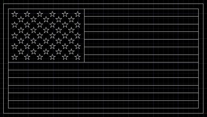
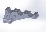
OK, looks like we can post up our cad files!

If possible, post a pic (jpg) of the file.

<PLEASE DO NOT POST DRAWINGS YOU DID NOT DRAW YOURSELF>

Lets observe the rule of "if you did not draw it, do not post it"

This will keep the forum mods and admins out of trouble and the thread open for all to utilize!

Admin and mods, please feel free to delete or modify any posts (attachments) you find that break any rules.

ENJOY!

WSS
 
#3 ·
Nice WSS,
What about stuff that isn't quite CJ specific? I drew up a wooden frame that I'll use to lift the motor out of myCJ, and also the US flag that I plan to cut out and use as a stencil to paint on the hood. Figured I'd ask first.
Thanks for the dash drawings too!
 
#4 ·
#6 ·
I just wanted to throw this out there for people that do not have access to CAD or are intimidated by it. Google Sketchup is an awesome program for home design use with a ton of support on the web including access to thousands of drawings. I am an engineer with a ton of experience in CAD and I use sketchup at home because of it's support. I used it to design my rear bumper. I found a drawing of a Jeep that someone had uploaded so that I could see my design on the vehicle before touching a piece of metal.
 
#14 ·
Here are some .jpg of some brackets that I did when I ran my fuel and brake lines. This was more of a custom job but maybe some of you can use it. I am attaching everything as a .jpg for now. Me and .dxf files don't get along so just shoot me a PM and I can e-mail you a step or parasolid file. Also notice that all but one of these clamps are not split in half. I used a wire EDM machine to cut these up and left a gap in the middle to compensate for the .010" thick wire plus spark gap (so if you need two separate drawings just take out .014" out of the middle). If anybody has any issues with the drawings let me know I can fix them up and make them easier.
 

Attachments

#24 ·
Trying to gauge interest on a CAD version of the wiring diagrams...

I'm about 60% done making a CAD file from one of the old jpeg images of a CJ wiring diagram. I'm guessing a live CAD file may be of use to some?

It would be especially handy if you have CAD and want to change things to match your existing Jeep... I plan to make each wire a polyline, meaning that if you select it in CAD then the whole wire is selected, from end to end. Guess we'll see, I've been chipping away at it when other Jeep stuff isn't more pressing.

I could post a work in progress if anyone wants to see what it looks like right now. If enough people would want it I could probably step up my attention to getting it done.

mock poll:
  • CAD files for wiring diagrams are pointless
  • CAD files for wiring diagrams would be the bomb!
  • I'd trade a ton of CJ parts for a CAD file of the wiring
  • I already have a CAD file for the CJ wiring, I just didn't share here
 
#25 ·
^^Bring it on!^^

Does not have to be loaded as a dxf, cad or dwg as it is for reference. A pdf or jpg is cool.

Are you doing "color correct" type of drawing?

If you post what you have, some may be able to critique it and give some suggestions too.

I have no idea w/electrical but am all up for learning about it and following along.
 
#26 ·
Right now I'm doing it like the factory diagrams. All the wires are one color, with wire numbers, color, and size labels. At the moment I've created layers for wiring, devices, text, optional items, vacuum lines, ported vacuum, title block, etc. I also just realized that I've been doing a '78 wiring diagram that has the glass AGC type fuses instead of a '79 or newer with the ATC type fuse block. My CJ is an 80 so I should have been doing a newer version for my own benefit. Dangit!

I'll clean the '78 drawing up a bit and post it, with a raster reference file. Once it's done it will be all digital, but for now you'll want to see the image portion for what I haven't drafted.
 
#27 ·
So, I just dropped in a different image for the drawing because the one I was using had "issues". Another slight glitch, the forum doesn't support uploading TIF images, so I'll be sure to post it again later with a JPG instead, for now it will be a broken reference. I noticed a few discrepancies so there is even less done than I thought. I had been doing just the 6 Cyl portion of the engine side, and planned to put the vacuum diagram in it's place for my own application. For now the vacuum portion is off to the side and the V8 wiring is untouched.

This is sounding less and less attractive all the time ;)

Just save the image and the CAD file to a folder on your PC (both to the same folder) and open the AutoCAD file.
 

Attachments

#29 ·
Here are the skid plate dxf's for a CJ5 intermediate (Mines a '72)

One piece is for guys with a wide press brake, the two piece is for guys with a swag brake. The sides gussets need two pieces cut to complete a skid plate.

Image


Image


cheesie fone pic
Image
 

Attachments

#30 ·
Here is dual Optima battery tray with hold downs. The two vertical hold downs are a little long so you can cut with a cut off saw or whatever you have to fit your particular length. I put a 1/4" piece of open celled rubber under mine. If you skip the rubber, yours will need to be shorter of course. One side (the outboard/pass side) on mine is hinged as it will be used for lend power at times, the hinge allows the batt to slide out and not have to be lifted straight up. You could hinge both sides or neither if you will leave them in all the time.

A is main tray with bend notches.
B is divider (w/ my logo, put in your own or pm for a custom one)
C is top clamp struts, you need two bent the same
D is long vertical arm
E is short vertical arm

cut one of each D and E or two of one depending on your needs. They are the same, just one is .25" longer and easy to trim to a custom length.

Cheers!

Image


Image


Image
 

Attachments

#31 · (Edited)
Headlight relays

From a discussion on another thread, here is a quick sketch of a way to hook up headlight relays, using CJ style wiring numbers and device depictions.

Edit
I've finally started adding a headlight relay kit to one of my Jeeps and I used the above drawing as a starting point. One think I quickly decided is that I didn't really want to chop up the factory lighting harness. My old CJ had a lighting kit added to it when I bought it, which allowed switching between two sets of lights with a toggle switch. The other set of lights was not present on the Jeep when I bought it so the switch always needed to be in one position for the headlights to work. The harness used an H4 plug out at the driver's side headlight socket to get power from the headlight switch and fed it through the harness. At some point the toggle switch failed and I needed to get the lights working. Since the harness was an add on to the factory wiring all I needed to do was pull the H4 plug and swap the headlights back to the factory lighting sockets. This is also how I would prefer to add my headlight relay wiring.

So, I chopped the H4 plug from the failed lighting harness and have been building an add-on headlight relay wiring kit. I revised the previous drawing to show the new details and made terminal numbers match the relays I purchased. The terminal numbers match a couple of different relays but probably won't match with all of the possible relays one could use.

The drawing includes a diagram of the relay function so that its operation can be copied to whichever relay is purchased. Suggested wire sizes are on each conductor as well as colors that match the factory CJ and YJ wire colors.

These additional files are my "pre-fab" versions. I'll plan to replace them with final versions should I make any changes during the build process.
 

Attachments