Jeep Enthusiast Forums banner

78 CJ7 Throwout Bearing / Linkage Upgrade

4.1K views 17 replies 4 participants last post by  InjectedCJ7  
#1 ·
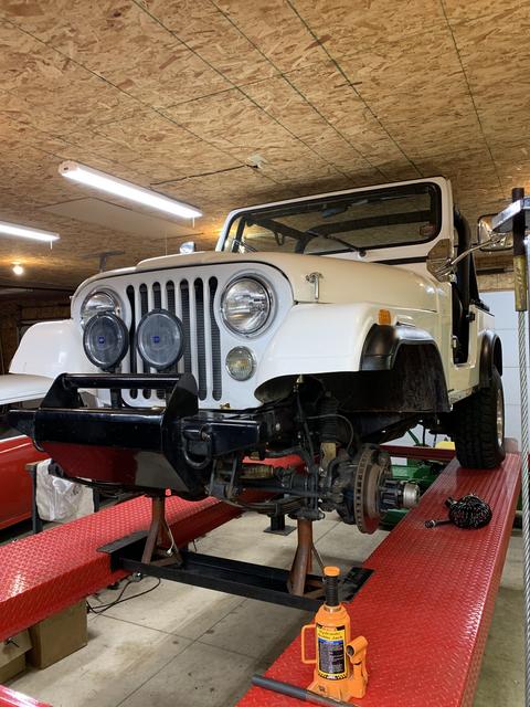
I'm starting this thread to help me with my plans to replace my throw out bearing in my 78 CJ7. It has a TPI 350 Chevy and a T18a 4-speed transmission. I currently have very noticeable noise from the bearing when engaged, and realize it's only a matter of time until it fails... A little background is in order, I believe.

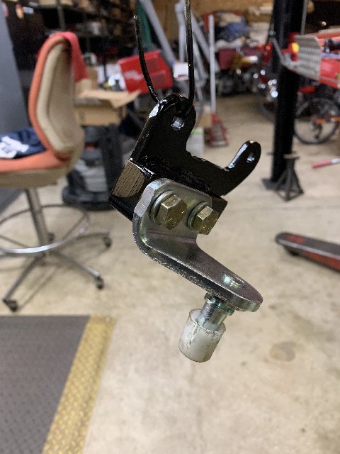
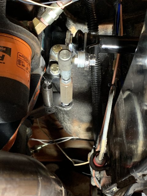
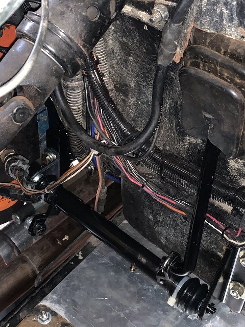
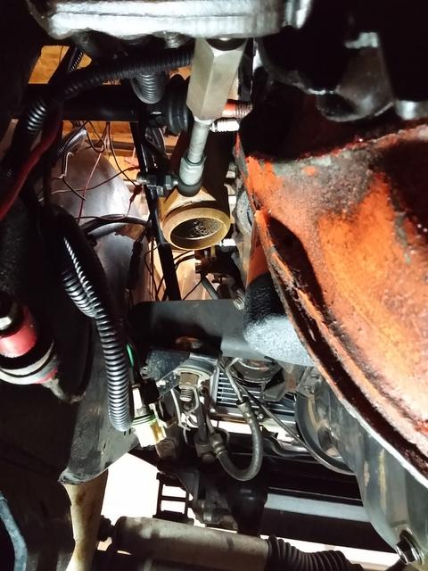
I bought this Jeep a few years ago, as a project in process. My build thread can be found here, for anyone who might be interested. When I got the Jeep, the driveline was already in place. I mostly worked on wiring and miscellaneous mechanical details. The clutch works OK, but the linkage is a bit suspect. There was a spring attached to the clutch fork, but it was installed in the wrong direction, actually pulling the bearing into contact with the pressure plate. This likely contributed to the bearing getting worn out. I reversed the spring, to try to get the bearing away from the pressure plate when not being used, but I believe the damage had already been done, as it sound 'dry' when engaging. The clutch fork boot is all ripped up too. The linkage is a bit sloppy, so I might decide to upgrade it with rod Heim joints, etc. I'm also considering changing over to a hydraulic actuation system, and would be interested in hearing your thoughts on that idea.

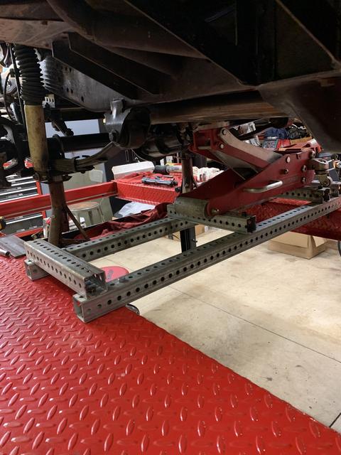
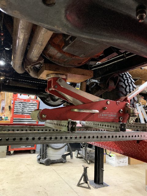
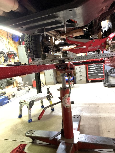
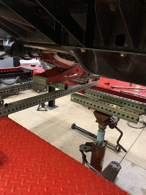
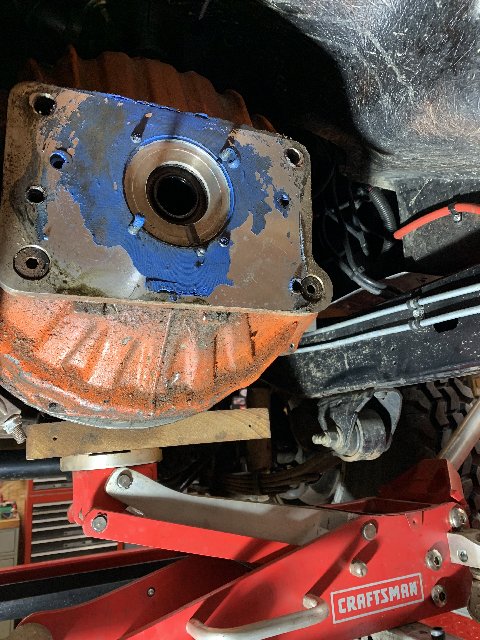
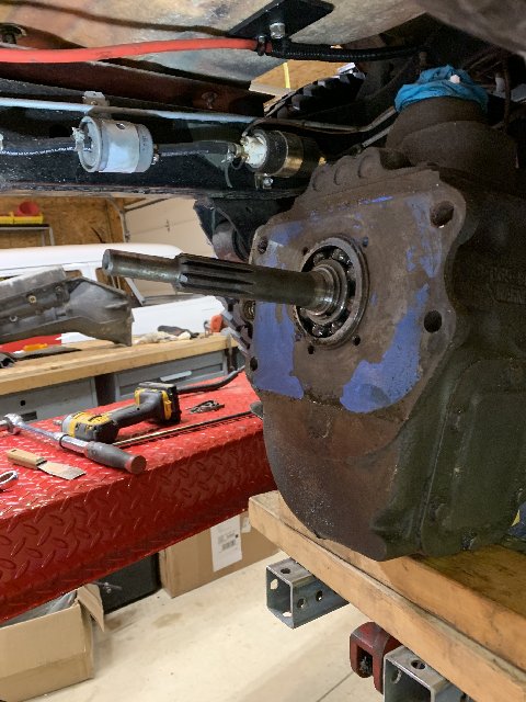
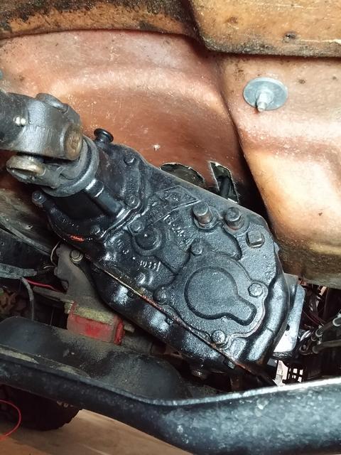
My first set of questions to the Forum experts are concerning the best approach to access the clutch. I'm thinking of blocking up the rear of the engine with the jack tray on my 4-post hoist, then pulling the skid plate (which is the rear cross member), followed by pulling the transfer case (after the drive shafts, of course). Then I would pull the transmission, after removing the shifter assembly from the top. Lastly, I would remove the clutch linkage and bell housing, exposing all my issues. Does this sound like a good approach? I'm open to any and all suggestions to help make this job go as smoothly as possible... Looking forward to your replies!

Regards,
John


#2 ·
I found the easiest way to access the clutch was to leave the trans/t-case/crossmember all in one piece. Remove the driveshafts and shifters and disconnect the electrical connections at the trans and t-case. Place a rolling floor jack under about the mid-point of the cross member with the handle of the jack pointing to the rear of the CJ. Remove the trans-to-bell housing bolts, then remove the cross-member bolts. Lower the jack just enough to allow you to slide the whole assembly rearward ( lower it maybe 1/8-1/4"). Don't lower the assembly to the ground, just slide it back far enough to clear the trans input shaft from the bell-housing. Then remove the bell-housing and install the new clutch parts. Reassemble in reverse order.

This method will save you a lot of time wrestling with the individual components. It also keeps the trans at the proper angle to easily stab it back into place.

Good luck,

Matt
 
#3 ·
Another question

I found the easiest way to access the clutch was to leave the trans/t-case/crossmember all in one piece. Remove the driveshafts and shifters and disconnect the electrical connections at the trans and t-case. Place a rolling floor jack under about the mid-point of the cross member with the handle of the jack pointing to the rear of the CJ. Remove the trans-to-bell housing bolts, then remove the cross-member bolts. Lower the jack just enough to allow you to slide the whole assembly rearward ( lower it maybe 1/8-1/4"). Don't lower the assembly to the ground, just slide it back far enough to clear the trans input shaft from the bell-housing. Then remove the bell-housing and install the new clutch parts. Reassemble in reverse order.

This method will save you a lot of time wrestling with the individual components. It also keeps the trans at the proper angle to easily stab it back into place.

Good luck,

Matt
Thanks, Matt. I'm finally getting around to this job, possibly this weekend. My question is, what is the easiest/best way to remove the transfer case shifter? I tried searching the forum, internet, etc, and can't really find any clear answers. Do you have a step by step procedure that works well for you? I don't want to just randomly remove bolts and cotter pins, hoping it all falls out... Thanks in advance!

Regards,
John
 
#7 ·
If you are cramped under the Jeep, you can put the rig on jack stands and gain some much needed maneuvering room.


Don't be afraid to strap/bolt the assembly to your jack before removal. Getting the skid plate (with the transmission/ t case attached) back on the pad after it slides off will cause you to curse your mother for bringing you into this world.
 
#8 ·
Jeepdaddy2000,
I actually have a 4-post hoist in my garage, but because of my roll cage and fairly low ceiling, I can't raise it as much as I would like. I'm going to strap the assembly to my transmission jack and hopefully be able to slide it out in one piece (after I figure out how to remove the t-case shifter). I hope to start on it tomorrow, and I'm sure I'll have more questions once I get started... I'll try to take some pictures to document the job.

Regards,
John

Here's some pictures from when I installed my front Spartan locker. I plant to use my floor jack cradle to be able to angle the rear of the engine when I go to reinstall the transmission.


#9 ·
Update!

I'm getting close to pulling the transmission/transfer case assembly. I figured it would be best to rest up and do the final work tomorrow, rather than pressing my luck today. I removed the t-case shifter by drilling a hole in the side of the tunnel, so the pivot bolt could be pulled out. I decided to drill a couple of holes in the skid plate to secure the transmission jack. I determined the center of gravity by the 'eyeball' method... The center of the transmission jack is around Where the trans meets the t-case. Should be close enough. My floor jack tray should allow me to adjust the engine angle to make removal/installation easier (I hope).

All that's left to do now is remove the skid plate bolts and lower the plate enough to clear the mufflers when I slide it out (maybe 2"). Then I'll pull the last trans to bell housing bolt out, and slide out the assembly. Sounds easy enough... Wish me luck!

Regards,
John


#10 ·
Update - MAJOR Issues...

Ok, this is going to be a pretty lengthy post, so grab a beer and get prepared...

I called my buddy to give me a hand pulling the trans/t-case, since there's a lot going on, and a lot of weight. We got the trans jack in place and bolted to the skid plate. Pulled the skid plate bolts and the trans to bell housing bolts. At this point the whole assembly should just slide out, right? Well, it wouldn't budge, despite lots of prying and cussing... At this point we noticed that there was RTV between the trans and the adapter plate, which seemed quite odd to us. I rigged up my slide hammer to the trans mount bracket (solid point) and with a few whacks it broke loose. The trans was indeed 'glued' to the adapter plate (see pictures below). The throw out bearing retainer was bolted to the other side of the adapter plate. It is also stuck on with lots of RTV. I measured the throw out bearing retainer flange OD which should pilot in the bell housing bore. Well, the flange diameter is 4.675" and the bell housing bore is 5.125". No piloting going on there... Next, I checked the fit of the throw out bearing to the retainer. Throw out bearing bore is 1-7/16", retainer OD is 1-3/8". Not good. Next I went to take a look at the pilot bushing in the crankshaft. There isn't one. That's correct, no pilot bushing...

So now, I have quite a bit of work ahead of me. I researched the Novak site, and it appears that they have the conversion parts I need to make this right. I didn't want to pull the clutch assembly off, but I'll need to, in order to install the pilot bushing.

Does anyone have any experience with the Novak kit, specifically for the GM to T18 trans? Any advice or experience would be greatly appreciated!

Thanks,
John


#11 ·
Update!

After researching the Novak site, I came up with a list of parts to make my Jeep right. I called Novak to discuss my plans with them, and we determined I needed the following parts:

- spacer ring between the bearing retainer and bell housing bore,
- adjustable throw out bearing
- correct clutch fork
- adjustable clutch fork pivot ball, and
- pilot bushing

With the adjustable pivot ball, adjustable throw out bearing and new clutch fork, I should be able to get the correct clearance and geometry for the system. I removed the pressure plate and clutch disc, and was happy to find the clutch and flywheel are in excellent condition, with virtually no wear. I measured the runout of the crankshaft pilot bearing bore, and it was about 0.0015", well within the desired maximum of 0.003" that Novak recommends.

The parts should arrive tomorrow, so I can start fitting things together. The clutch linkage needs some repair as well, but I'll save that discussion for the next update. Stay tuned!

Regards,
John
 
#13 ·
John,
My adapter plate looks similar to this, but with less holes, and a bit smaller size. I tried searching for the casting number on mine, but couldn't find anything. Regardless, it seems like it will work fine, with the repairs/updates I'm adding. I installed the correct pilot bushing, and laid out the position to ensure it will line up properly with the input shaft when installed. Today, as I continue with my Coronavirus Garage Quarantine, I plan to reinstall my clutch and set up the new adjustable Novak throw out bearing, along with the new adjustable pivot ball, and new clutch fork. When this is done, I plan to mount the adapter and bell housing to the transmission, in preparation for final installation back to the engine.

I have a question for the Forum. While examining my clutch pedal linkage, I discovered that the block-side pivot stud was actually just a 1/2"-13 bolt with the head cut off... it stuck out about 3" from the block, and was riding (actually flopping around) inside what was left of the nylon bushing. I'm running a 350 Chevy, so the stud (bolt, in my case) threads directly into the block. I'm guessing that a stock stud may not be long enough to work with the stock cross shaft, base on how long the bolt was. I've been searching the various suppliers, looking for a stud with the correct size ball on the end to work with the stock nylon bushing, namely 5/8". For some reason, NONE of the suppliers state what size the ball diameter is. I can adapt the length, no problem. But I don't want to buy a stud, in order to figure out what size it is! Looking at all the pictures of the GM studs, the ball diameter looks too large. Can anyone help me figure out how to get the stud I need? Any help would be greatly appreciated!

Regards,
John
 
#16 ·
John,
Thanks for the detailed answer! I’m pretty sure this is the most common screw-in stud being sold. The ball diameter (0.870”) is way too large for the CJ bellcrank shaft. I need to find one with a 0.625” diameter ball somewhere... The search goes on. I would consider buying one of the engine side bracket/ball assemblies that are made to bolt to the bell housing and adapting the ball portion. But, I’d still like to confirm it’s the right size before I buy one.

Thanks again,
John
 
#17 ·
Update!

Well, I'm still plugging away at my clutch, waiting for a few more parts to arrive. The more I try to piece together my random mix of Jeep and Chevy hardware, the more clear it becomes that I'm going to have to re-engineer the system... The CJ bellcrank has unequal length legs on each end. This bellcrank can be installed in either orientation (correction - the long leg side is designed to be installed on the clutch pedal side. The bushing bore on that side is deeper, and the ball pivot shaft is longer, to allow the bushing to travel side to side with engine movement). The difference will be the ratio of travel from the pedal to the fork. One of my main concerns is that the pushrod from the bellcrank to the clutch fork in on a significant downward angle, even with the long leg of the bellcrank oriented to the engine side. Confused yet? When I look online at Chevy bellcranks, they have much longer legs than the CJ version. The longer leg at the engine side would make the angle of the push rod much more perpendicular to the fork (parallel to the ground), which in my mind is necessary. However, buying a Chevy bellcrank just adds another mismatched component to the mix, where my pivot balls, etc wouldn't fit.

So, what I plan to do is re-design the system from the throw out bearing back to the clutch pedal. I plan to use my bellcrank tube and the CJ pivot balls as a starting point. From the Novak site, the GM diaphragm clutch needs about 0.55" travel of the throw out bearing to release. If I get my bearing clearance set, and my pushrod angle level, I can determine the position and length of the engine side leg. Then, I can determine the body side leg length needed to produce the desired pushrod travel when moving the clutch pedal through its travel. I plan to lay this out on paper and double-check my calculations before I start chopping up my bellcrank. I'm pretty sure this is the only way I'm going to get the mechanical linkage working properly. I've got a MIG welder, a band saw, and thanks to the F****** Coronavirus, some spare time, so maybe I'll be able to solve this problem... I welcome anyone's ideas and suggestions. Oh, and by the way, I strongly considered going with a hydraulic system, but looking at my firewall and clutch pedal, I think that might be even more work.

Regards,
John
 
#18 · (Edited)
Update - Complete!

As is the case with most (if not all) Jeep projects, what should have been a straightforward throw out bearing change turned into a major job... I already highlighted some of the issues I discovered with the linkage, leading me to conclude that I would need to rework the bellcrank, as well as the engine side pivot. When I dug a little deeper, I discovered that the PO used an engine side pivot on the body side, which raised the bellcrank more than an inch, to align it with a threaded hole in the side of the 350 block. At this height, the clutch rod was on a severe downward angle to get to the clutch fork. I bought the correct body side mount, and fabricated an engine side mount bracket which bolts to the bell housing. This brought the bellcrank down to the correct height, which then made the clutch rod almost level going back to the clutch fork. The next issue was that the PO cut a section out of the pedal rod to account for the raised up bellcrank. So, I broke out the MIG welder and welded in a 3" piece, and did some tweaking to the bends in the rod to get things lined up to my liking. I also added springs to keep the clutch rod in contact with the clutch fork, and to keep the clutch pedal up against it's stop when released. The only issue I wasn't sure of was if the total throw of the clutch fork would be correct, since the new Novak clutch fork has a slightly different ratio from the one I removed. With everything lubed up, I crossed my fingers and fired it up. It appears that everything is working properly, although I only had a chance to take it up my street and back. The growling noise from the worn out throw out bearing was gone, and the linkage feels pretty smooth. At this point, I'm declaring victory!

On to the next project...

Regards,
John