Heater motor Fix.
The problem:
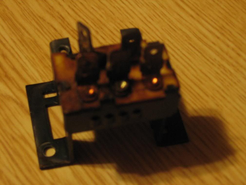
Blown heater motor resister, melted speed switch, melted wires in steering column
The Fix:
Adding relays in the heater circuit. You will also need to replace your blower motor resistor, and selector switch if you have not already done so.
Parts Needed:
4 relays
10 feet red 12 gauge wire
2 feet black 12 guage wire
assorted crimp connectors
1 fuse holder (30A)
Background:
When I got my jeep the heater resistor was blown, so I replaced it. Next, whenever I would Use the A/C a wire near my ignition switch would begin to heat up and smoke. I then discovered that the blower speed switch was melted. I replaced that, but the smoking continued. I then began to research a solution.
Basically, as the blower motor ages it begins to be less efficient and the motor draws more amps. When that happens, the resistor blows, and typically the blower motor switch begins to melt. The factory wiring for this particular circuit is marginal at best, and just simply overloads as the motor ages.
With that in mind, I hit the junkyard to find a new switch pigtail as it seems the connector melts. I looked at 10-12 cherokees in the yard (every one they had) and all the switches were melted. What does that tell you?
That's when I decided to fix the problem. I didn't want to need to Plan on a new fan ($30), switch ($30) in the future.
Reference:
http://www.jpmagazine.com/techarticles/electrical/154_0710_jeep_fire_prevention/index.html
http://www.naxja.org/forum/showthread.php?t=88091&page=2&highlight=blower+motor+relay
http://www.jeepforum.com/forum/showthread.php?t=564106
How the circuit works:
(simplified version)
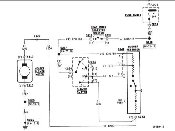
When the key is turned on, the circuit is energized at the ignition switch. Power then flows from the fuse box to the blower mode switch to the speed selector switch. Once the speed is selected, power then flows to the appropriate wire in the blower motor resistor, and finally to the blower motor. What I chose to do was to put relays inline between the blower motor switch and resistor.
Here is the relevant part of the diagram:
![Image]()
We will basically be adding relays to the following 4 wires located at the blower motor resistor:
Yellow/brown, Tan, Light Blue, and Green.
I used relays already wired with a pigtail from summit racing this makes wiring easier and everything is color coded:
http://store.summitracing.com/partdetail.asp?autofilter=1&part=VIA-80237&N=700+115&autoview=sku
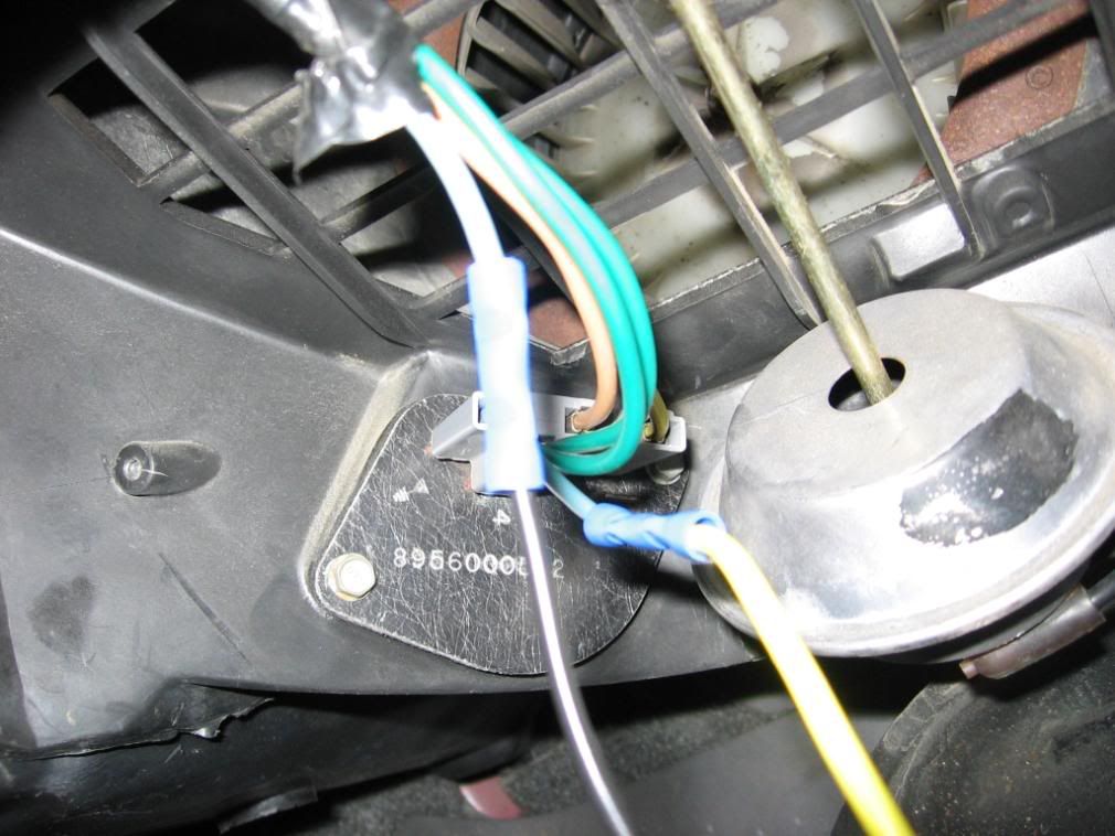
First, locate your blower motor resistor underneath the passenger kickpanel, you will see all the wires we need:
![Image]()
Then, you need to cut each of the 4 wires on that connector, and wire in the relay:
![Image]()
Basically, all 4 relays will share a common ground and power. Then they have a
"signal" wire, and a "load" wire. The signal wire needs to be wired to the wire coming from the switch, and the load wire needs to be wired to the part of the wire going to the blower motor resistor.
The only problem here is the Dark green wire in the harness there are actually 2, which are spliced at the resistor connector. 1 comes from the selector switch, 1 goes to the blower motor. You need to put a relay on the one coming from the switch. To figure out which one this is, I snipped one (lucky guess) turned on the blower motor to high, and used a voltmeter to determine that the one I snipped was getting power, which means it is the wire from the switch. If you snipped that one that is not powered, splice it back together and snip the other one.
All relays have numbered terminals, the terminal numbers, and wire colors from my relays are below:
Pin Purpose Color
38 power blue
86 ground white
85 signal black
87 load red
Note, if your relays have 5 terminals, one will be numbered 87a, simply do not use it.
If you would like a tutorial on what relays are/ do, please read here:
http://www.naxja.org/forum/showthread.php?t=933445&highlight=relay+wiring
Once you have all the relays splice in, you will need to solder together the 4 power wires, and then the 4 ground wires. You now need to find a power / ground.
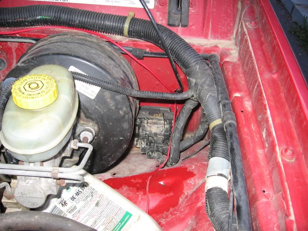
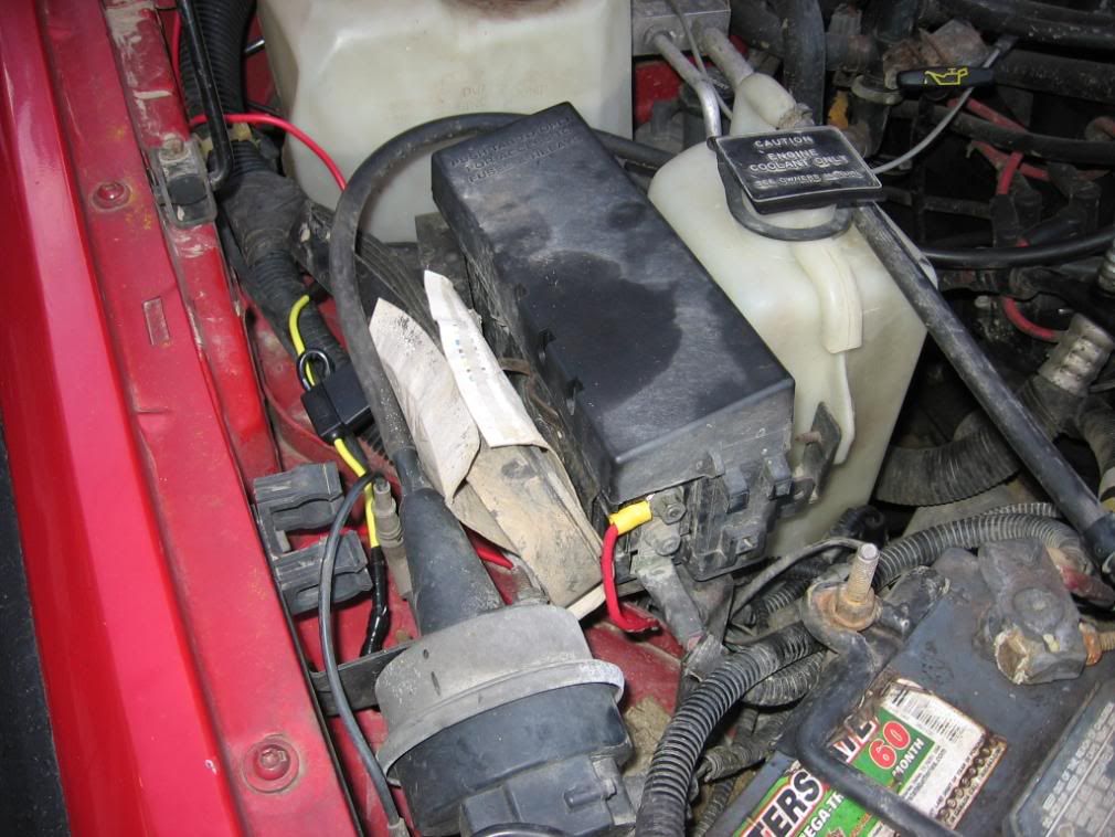
For the power:
Solder it to the 4 soldered power wires, and then run it under the dash to the drivers side, right above the fuse box you should find a hold in the firewall. Run it through there, across the engine bay, and tie it into the auxiliary power post. Be sure to put a fuse in this circuit (30A):
![Image]()
![Image]()
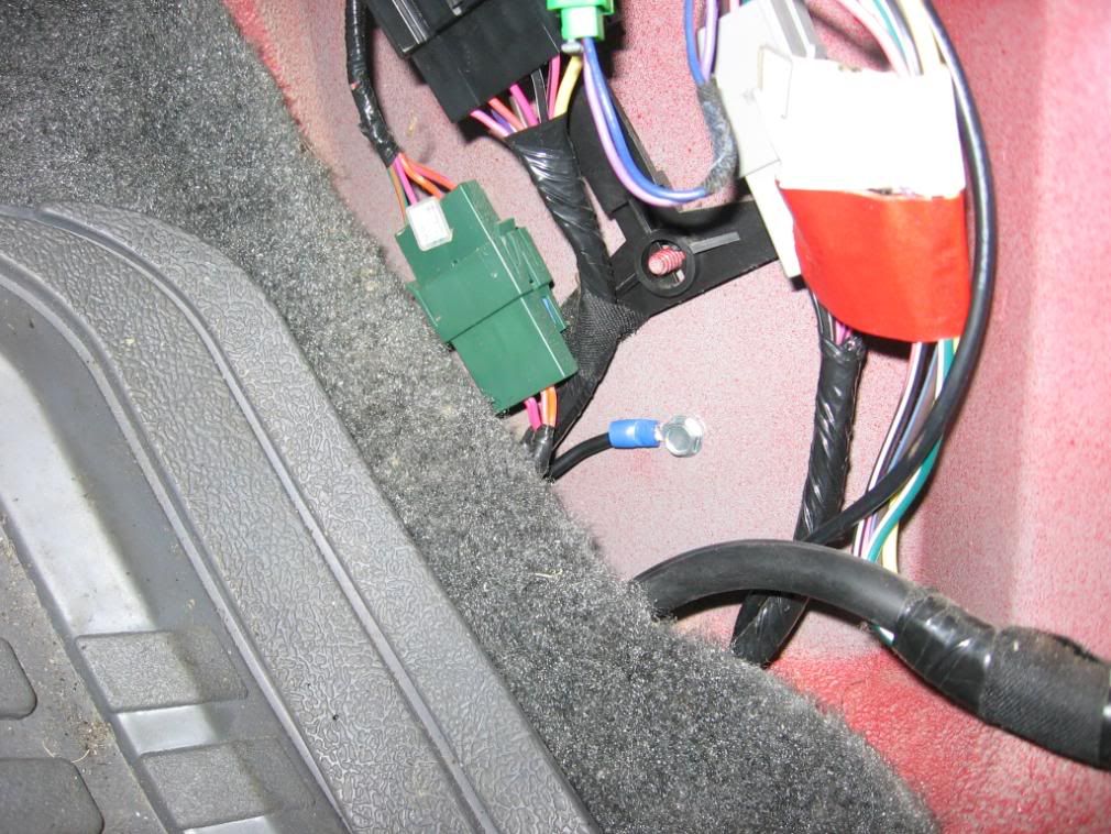
For the ground.
Once again, solder a ground wire to the 4 soldered ground wires. Then, I pulled the passenger side kickpanel off. Use a self tapping screw to drill a hole in the sheetmetal. Crimp a ring connector on your wire, and tighten it down:
![Image]()
Tape, everything up, then shove all the relays up under the dash. There is plenty of room:
![Image]()
Once your done you won't even see it. Full Power will be restored to your blower motor, and no more burnt wires, switches, resistors. And best of all, no chance of fire.
Total cost was about $35.
special thanks to balloo93 who helped me understand this circuit when I was troubleshooting my original problem.
The problem:
Blown heater motor resister, melted speed switch, melted wires in steering column
The Fix:
Adding relays in the heater circuit. You will also need to replace your blower motor resistor, and selector switch if you have not already done so.
Parts Needed:
4 relays
10 feet red 12 gauge wire
2 feet black 12 guage wire
assorted crimp connectors
1 fuse holder (30A)
Background:
When I got my jeep the heater resistor was blown, so I replaced it. Next, whenever I would Use the A/C a wire near my ignition switch would begin to heat up and smoke. I then discovered that the blower speed switch was melted. I replaced that, but the smoking continued. I then began to research a solution.
Basically, as the blower motor ages it begins to be less efficient and the motor draws more amps. When that happens, the resistor blows, and typically the blower motor switch begins to melt. The factory wiring for this particular circuit is marginal at best, and just simply overloads as the motor ages.
With that in mind, I hit the junkyard to find a new switch pigtail as it seems the connector melts. I looked at 10-12 cherokees in the yard (every one they had) and all the switches were melted. What does that tell you?
That's when I decided to fix the problem. I didn't want to need to Plan on a new fan ($30), switch ($30) in the future.
Reference:
http://www.jpmagazine.com/techarticles/electrical/154_0710_jeep_fire_prevention/index.html
http://www.naxja.org/forum/showthread.php?t=88091&page=2&highlight=blower+motor+relay
http://www.jeepforum.com/forum/showthread.php?t=564106
How the circuit works:
(simplified version)
When the key is turned on, the circuit is energized at the ignition switch. Power then flows from the fuse box to the blower mode switch to the speed selector switch. Once the speed is selected, power then flows to the appropriate wire in the blower motor resistor, and finally to the blower motor. What I chose to do was to put relays inline between the blower motor switch and resistor.
Here is the relevant part of the diagram:
We will basically be adding relays to the following 4 wires located at the blower motor resistor:
Yellow/brown, Tan, Light Blue, and Green.
I used relays already wired with a pigtail from summit racing this makes wiring easier and everything is color coded:
http://store.summitracing.com/partdetail.asp?autofilter=1&part=VIA-80237&N=700+115&autoview=sku
First, locate your blower motor resistor underneath the passenger kickpanel, you will see all the wires we need:
Then, you need to cut each of the 4 wires on that connector, and wire in the relay:

Basically, all 4 relays will share a common ground and power. Then they have a
"signal" wire, and a "load" wire. The signal wire needs to be wired to the wire coming from the switch, and the load wire needs to be wired to the part of the wire going to the blower motor resistor.
The only problem here is the Dark green wire in the harness there are actually 2, which are spliced at the resistor connector. 1 comes from the selector switch, 1 goes to the blower motor. You need to put a relay on the one coming from the switch. To figure out which one this is, I snipped one (lucky guess) turned on the blower motor to high, and used a voltmeter to determine that the one I snipped was getting power, which means it is the wire from the switch. If you snipped that one that is not powered, splice it back together and snip the other one.
All relays have numbered terminals, the terminal numbers, and wire colors from my relays are below:
Pin Purpose Color
38 power blue
86 ground white
85 signal black
87 load red
Note, if your relays have 5 terminals, one will be numbered 87a, simply do not use it.
If you would like a tutorial on what relays are/ do, please read here:
http://www.naxja.org/forum/showthread.php?t=933445&highlight=relay+wiring
Once you have all the relays splice in, you will need to solder together the 4 power wires, and then the 4 ground wires. You now need to find a power / ground.
For the power:
Solder it to the 4 soldered power wires, and then run it under the dash to the drivers side, right above the fuse box you should find a hold in the firewall. Run it through there, across the engine bay, and tie it into the auxiliary power post. Be sure to put a fuse in this circuit (30A):
For the ground.
Once again, solder a ground wire to the 4 soldered ground wires. Then, I pulled the passenger side kickpanel off. Use a self tapping screw to drill a hole in the sheetmetal. Crimp a ring connector on your wire, and tighten it down:
Tape, everything up, then shove all the relays up under the dash. There is plenty of room:

Once your done you won't even see it. Full Power will be restored to your blower motor, and no more burnt wires, switches, resistors. And best of all, no chance of fire.
Total cost was about $35.
special thanks to balloo93 who helped me understand this circuit when I was troubleshooting my original problem.