

Here's a how-to on removing the old fuel pump, filter, check valve, etc. assembly for a ZJ. The most important part of the installation is having the least amount of gasoline in the tank as possible. It makes lowering and lifting the tank much easier. (1 gallon of gas = about 6 pounds) Of course this guide can also be used for just removing the tank for whatever reason and not having to deal with the fuel pump.
Note: This was done on a 1997 Limited with the tow package. ZJ's without the towpackage will have easier time and install due to not having to removing the towing support brace and maybe the fuel tank guard (unsure about this.)
Install Time: 2-4 hrs. (depending on break times and assistance)
What you need:
- Ratchet
- Extension
- Flathead screwdriver (small/large)
- 18mm long socket
- 14mm open end
- 8mm open end or socket
- 6mm open end or socket
- Jackstands (very helpful, especially if doing yourself)
- Floor jack (very helpful, especially if doing yourself)
- Bolt degreaser (your choice, if wanted)
- Fire repellent/extinguisher handy
Ok lets get started. Once again you have the option to alter some of these stages.
**Notice - you're dealing with the fuel assembly which of course if highly flammable. So taking precautions is always wise. Your choice to disconnect the battery or not, might as well to be safe as static electricity and flammable fuel don't exactly mix with an awesome result. Especially if your laying next to it while it combusts.
1. Getting started
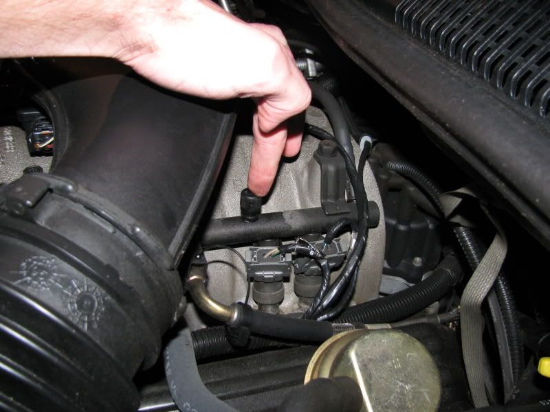
- Open your hood and disconnect the battery, just the negative terminal will do. Throw a rag/cloth over the battery just in case any type of metal might happen to fall hit the positive terminal. Now you will want to depressurize the fuel sending line. On the driver side fuel line there is a black cap located on top near the back two injectors, which is called a Schrader valve, and you will need to unscrew the cap and use a screwdriver or your finger to press the needle down until all the fuel pours out. You may want to place a rag underneath so fuel doesn't get all over your intake manifold. (If you're check valve was shot like mine was, you don't need to do this, as you should have little to no pressure) Next open your gas cap to vent the rear. You may want to lay some mat or carpet of your choice depending on what you have available since you will be spending the majority of your time on your back if you don't have access to a lift. Otherwise if you have a lift this entire installation will go much smoother.
- I personally didn't jack up the rear on jackstands but you have the option to easily by placing them under the axle as they will be out the way as you will be working from the axle back. I was able to do the install without, although it was very tight quarters.
Fuel pressure release valve:
![Image]()
2. Removing Tow Package Bolts (Non tow-package vehicles go to step 3)
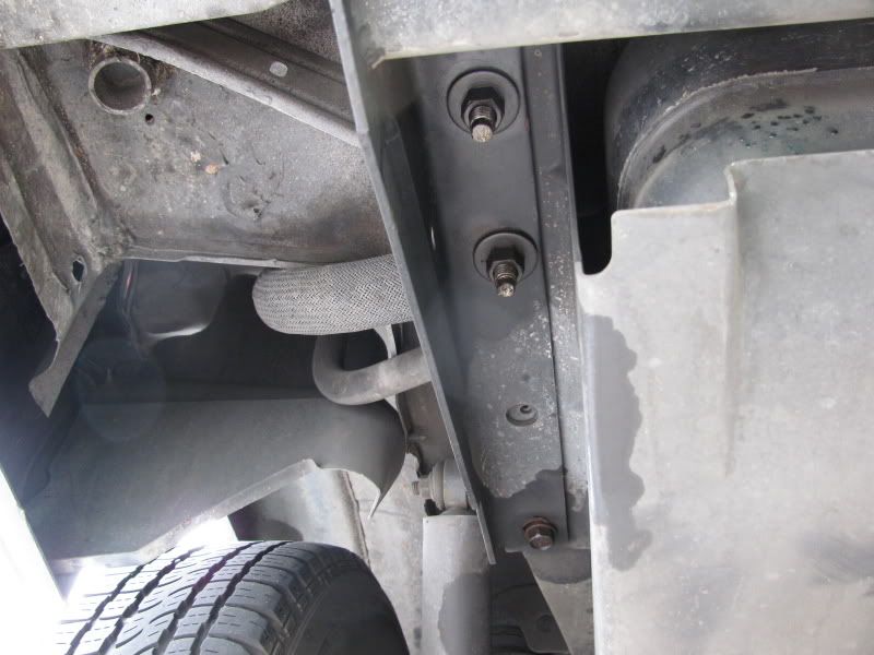
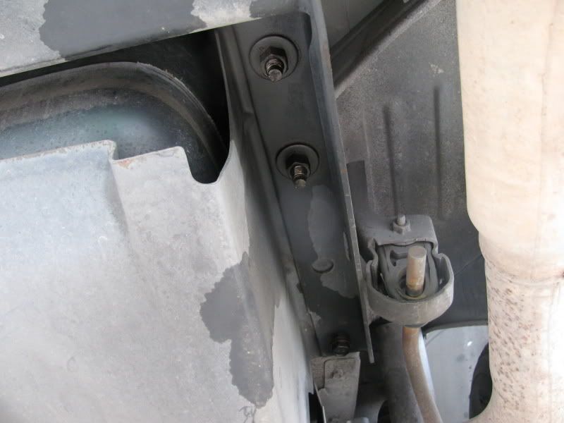
- You may or may not want to spray the bolts with degreaser depending on how corroded your bolts are. These are all 18mm in size with three on each side. The one closest to the axle is an actual bolt with an attached nut that comes completely out. The other two, the middle and closest one to the rear, are just nuts that spin free. Before removing all the bolts make sure you have the towing brace and fuel tank guard stabilized or supported. These parts are relatively heavy.
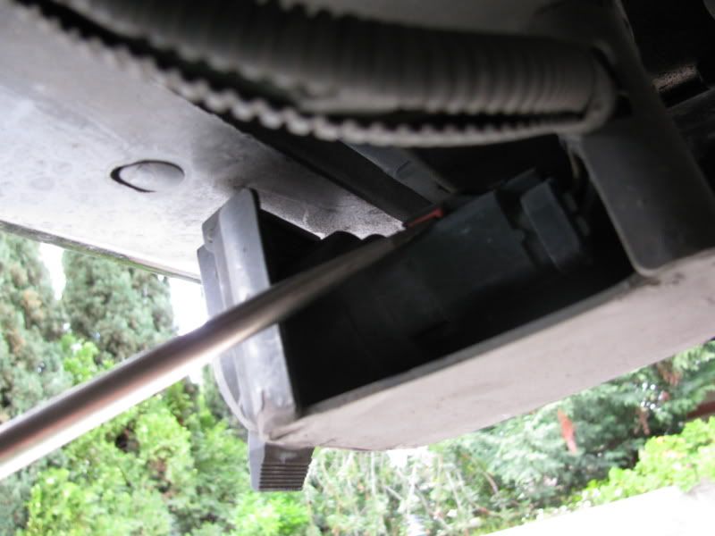
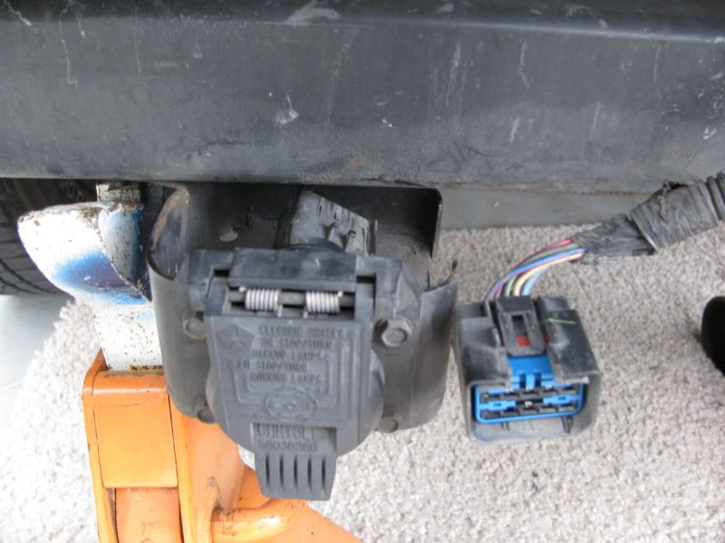
- You will also need to disconnect the electrical clip next to the hitch. There's a red safety clip inside this clip, be careful when disconnecting. Now you will want to most likely remove all the bolts except the one bolt in the middle on each side. (for stress and binding issues) Choose which side to remove either bolt next and make sure the opposite is fairly threaded out to help in removal. Brace for impact! Once removed put these parts to the side.
Driver side bolts:
![Image]()
Passenger side bolts:
![Image]()
Tow electrical outlet:
![Image]()
Tow electrical outlet disconnected:
![Image]()
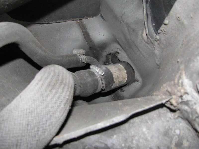
3. Unbolting Filler & Vent Tubes
- There's two hoses coming out of the driver side rear portion of the tank. Both of these will need to be unbolted most likely from both ends. Up near the gas filler hatch the tubes are slipped over the mount and held with metal straps. These same straps are down by the tank holding the hoses in place. Factory I believe these straps near the tank have the threads on top which are impossible to reach. So the top near the filler hatch need to be unbolted first. The top metal straps need either a 8mm open end/socket or a flathead screwdriver to open and allow the hose to slip off. Have fun with this part as those hoses are relatively difficult to pry off. Leave the one's by the tank connected until the tank is dropped, once you have the tank dropped you can rearrange these straps for easier access next time.
Hoses connected to filler mount:
![Image]()
Hoses connected to gas tank:
![Image]()
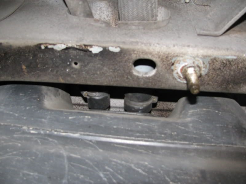
4. Dropping The Tank
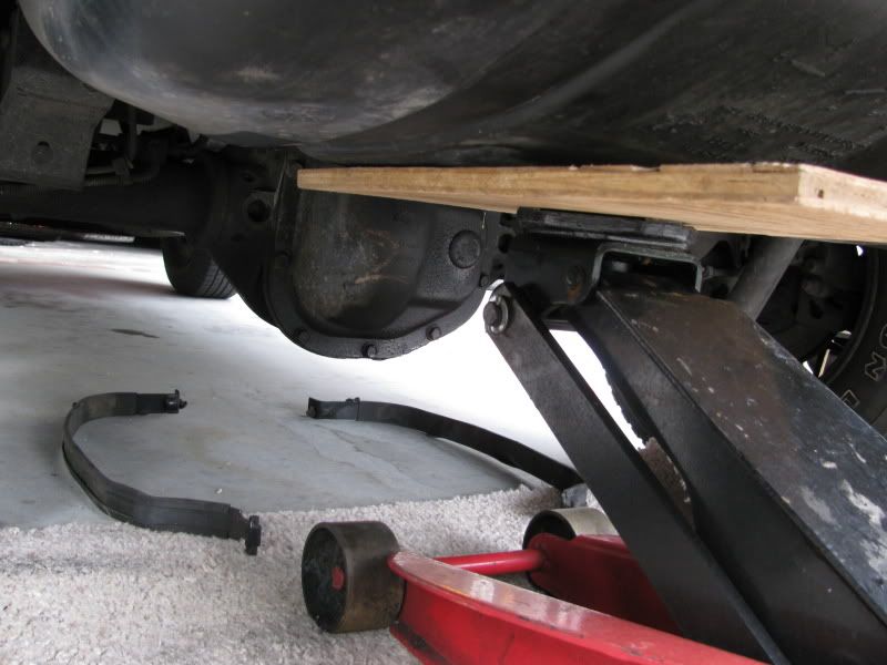
- The gas tank is held on by two supportive straps. These come completely off. Support the gas tank especially if the tank is carrying excessive gasoline as it can be quite heavy. Near the axle the nut bolts are 14mm and are basically just hanging from a hole in the frame, as these get lifted up to be released. On the other side of the strap, near the bumper, they are basically a "T" bar end and swing out sideways to be released. Again make sure your tank is supported as it's coming down once both of those straps are disconnected near the axle. You might be able to lower it down completely while feeding the filler hoses through the frame. Otherwise now you will have more room to disconnect these filler hoses near the tank to completely have them disconnected. You can lower the tank all the way down now and don't have to worry about any lines, or sensors binding or breaking as all the lines come from the front of the vehicle and nothing is connect to the frame near top of the tank. Just don't lower it and push it toward the rear of the vehicle.
Strap bolts near axle side:
![Image]()
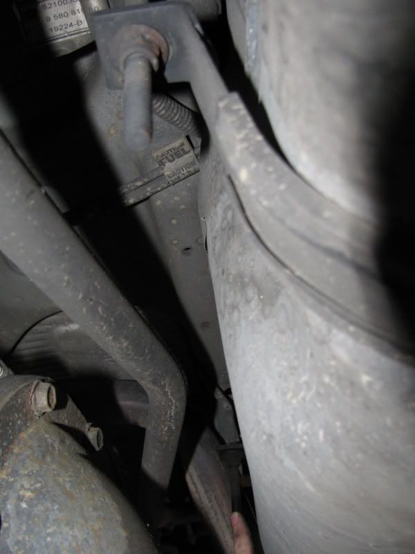
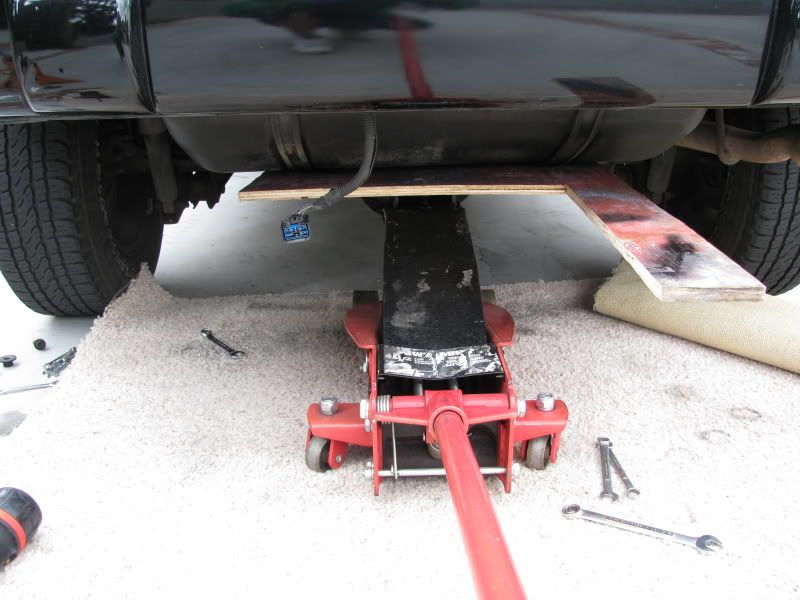
Tank supported:
![Image]()
![Image]()
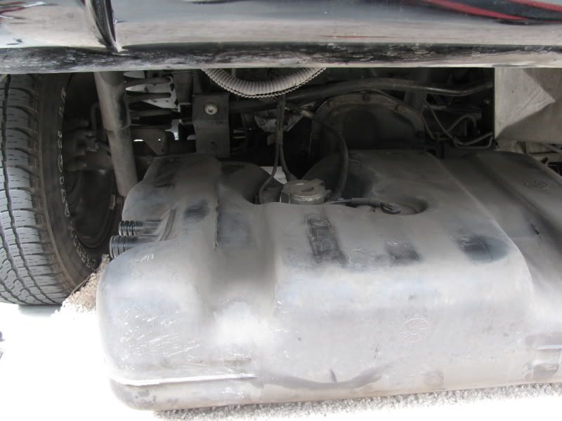
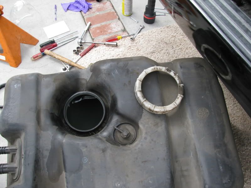
Gas tank laying on the ground:
![Image]()
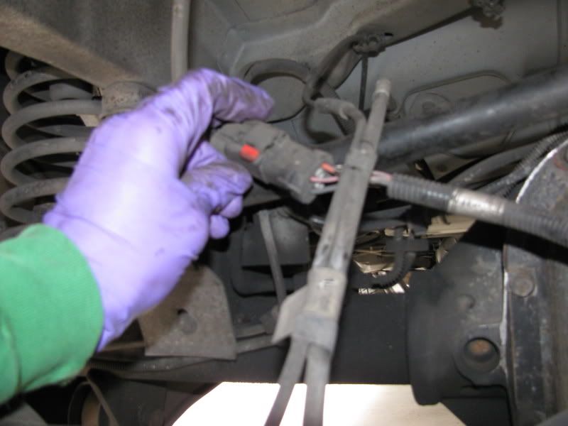
5. Removing Fuel Pump Connector Clips
- There's only two connections you have to worry about removing to get the pump assembly out. One is an electrical clip that has a red plastic safety slip which is for your gauge levels, etc. that is located up near the axle. The other is the fuel sending line which is also held on by a blue double snap plastic ring on top of the pump. (Be prepared for all of the fuel in this line to dump out as there should be a good amount stored in it) Both of these connector clips will have to be removed and un-clipped. To get a better idea, you can look at your new pump for more of an understanding. Note: You will see an arrow pointing forward and take note of the configuration of everything on top of the fuel pump assembly as your new one should look like just like the current one in the tank. You will want to completely remove the blue clip from the pump as it will be used later for your new pump.
Note: If you wish to fully remove the tank to make things easier, the other line, which is the fuel return line, is just attached by a hose which easily slips out. Otherwise the pump can be removed with just the other two clips disconnected.
Electrical connector clip:
![Image]()
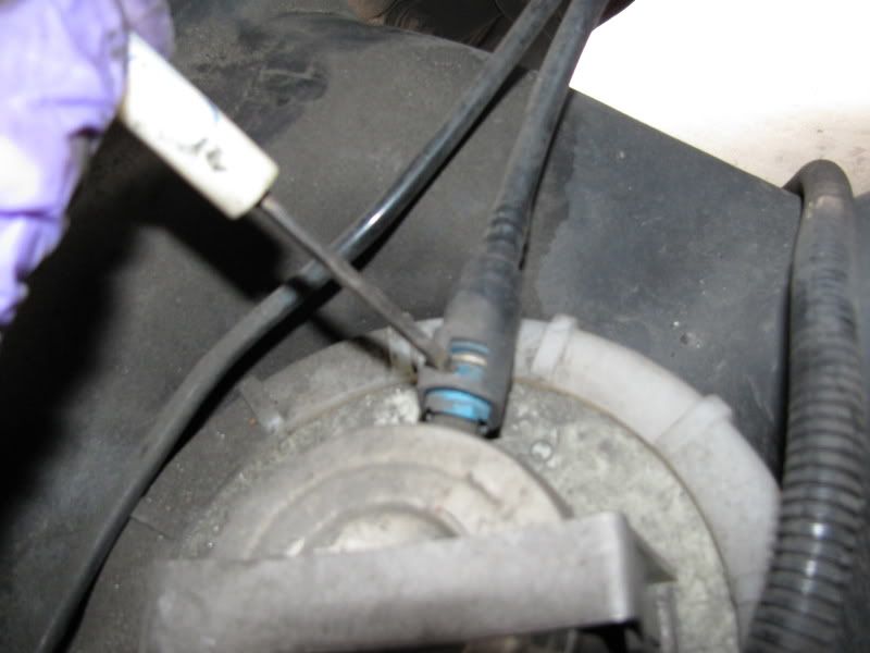
Fuel sender clip:
![Image]()
6. Removing Pump From The Tank
- Your almost there! This last part can be quite annoying for some. It's actually rather simple. Note that the pump has a white/ridged ring around it. This is actually threaded onto the tank to hold the pump down. If your able to turn it counter-clockwise with your hands your lucky as it's not very tight. Otherwise a flathead screwdriver and mallet will work by driving/tapping the flathead end sideways onto one of the ridges to help out. Once off just pull the pump out and dispose. Make sure you remove the black o-ring gasket as your new pump should be supplied with one and that blue plastic clip from the sender line is off.
Old pump and new one:
![Image]()
Open pump hole:
![Image]()
7. Installing New Pump
- Connect the blue plastic clip to the new fuel pump outlet. Once again, make sure the old black gasket is removed and the new one is on. The pump assembly is a self adjusting pump, so it's spring loaded. When you drop it in the hole, you will want to hold it down as it will want to spring back up. Make sure that the black gasket is not catching on the edges and is smoothly sealed all around. Go ahead and thread the plastic white ridged holder piece back on and tighten down a good amount... and your all done! Well not quite but your only going downhill from this point as everything has already been affiliated with.
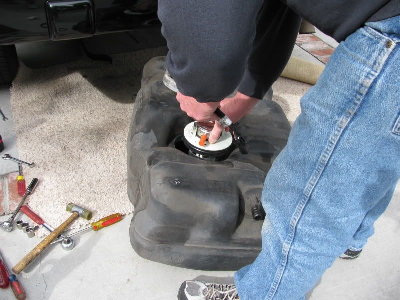
Dropping new pump:
![Image]()
So from here just repeat all the steps backwards and you've installed your new fuel pump assembly. A key word of advice is for those with the towing package... go ahead and fire it up before you put the towing bracket and fuel tank guard on to check for any leaks. If no leaks and it runs than go ahead and continue on as your almost there!
Note: This was done on a 1997 Limited with the tow package. ZJ's without the towpackage will have easier time and install due to not having to removing the towing support brace and maybe the fuel tank guard (unsure about this.)
Install Time: 2-4 hrs. (depending on break times and assistance)
What you need:
- Ratchet
- Extension
- Flathead screwdriver (small/large)
- 18mm long socket
- 14mm open end
- 8mm open end or socket
- 6mm open end or socket
- Jackstands (very helpful, especially if doing yourself)
- Floor jack (very helpful, especially if doing yourself)
- Bolt degreaser (your choice, if wanted)
- Fire repellent/extinguisher handy
Ok lets get started. Once again you have the option to alter some of these stages.
**Notice - you're dealing with the fuel assembly which of course if highly flammable. So taking precautions is always wise. Your choice to disconnect the battery or not, might as well to be safe as static electricity and flammable fuel don't exactly mix with an awesome result. Especially if your laying next to it while it combusts.
1. Getting started
- Open your hood and disconnect the battery, just the negative terminal will do. Throw a rag/cloth over the battery just in case any type of metal might happen to fall hit the positive terminal. Now you will want to depressurize the fuel sending line. On the driver side fuel line there is a black cap located on top near the back two injectors, which is called a Schrader valve, and you will need to unscrew the cap and use a screwdriver or your finger to press the needle down until all the fuel pours out. You may want to place a rag underneath so fuel doesn't get all over your intake manifold. (If you're check valve was shot like mine was, you don't need to do this, as you should have little to no pressure) Next open your gas cap to vent the rear. You may want to lay some mat or carpet of your choice depending on what you have available since you will be spending the majority of your time on your back if you don't have access to a lift. Otherwise if you have a lift this entire installation will go much smoother.
- I personally didn't jack up the rear on jackstands but you have the option to easily by placing them under the axle as they will be out the way as you will be working from the axle back. I was able to do the install without, although it was very tight quarters.
Fuel pressure release valve:
2. Removing Tow Package Bolts (Non tow-package vehicles go to step 3)
- You may or may not want to spray the bolts with degreaser depending on how corroded your bolts are. These are all 18mm in size with three on each side. The one closest to the axle is an actual bolt with an attached nut that comes completely out. The other two, the middle and closest one to the rear, are just nuts that spin free. Before removing all the bolts make sure you have the towing brace and fuel tank guard stabilized or supported. These parts are relatively heavy.
- You will also need to disconnect the electrical clip next to the hitch. There's a red safety clip inside this clip, be careful when disconnecting. Now you will want to most likely remove all the bolts except the one bolt in the middle on each side. (for stress and binding issues) Choose which side to remove either bolt next and make sure the opposite is fairly threaded out to help in removal. Brace for impact! Once removed put these parts to the side.
Driver side bolts:
Passenger side bolts:
Tow electrical outlet:
Tow electrical outlet disconnected:
3. Unbolting Filler & Vent Tubes
- There's two hoses coming out of the driver side rear portion of the tank. Both of these will need to be unbolted most likely from both ends. Up near the gas filler hatch the tubes are slipped over the mount and held with metal straps. These same straps are down by the tank holding the hoses in place. Factory I believe these straps near the tank have the threads on top which are impossible to reach. So the top near the filler hatch need to be unbolted first. The top metal straps need either a 8mm open end/socket or a flathead screwdriver to open and allow the hose to slip off. Have fun with this part as those hoses are relatively difficult to pry off. Leave the one's by the tank connected until the tank is dropped, once you have the tank dropped you can rearrange these straps for easier access next time.
Hoses connected to filler mount:
Hoses connected to gas tank:
4. Dropping The Tank
- The gas tank is held on by two supportive straps. These come completely off. Support the gas tank especially if the tank is carrying excessive gasoline as it can be quite heavy. Near the axle the nut bolts are 14mm and are basically just hanging from a hole in the frame, as these get lifted up to be released. On the other side of the strap, near the bumper, they are basically a "T" bar end and swing out sideways to be released. Again make sure your tank is supported as it's coming down once both of those straps are disconnected near the axle. You might be able to lower it down completely while feeding the filler hoses through the frame. Otherwise now you will have more room to disconnect these filler hoses near the tank to completely have them disconnected. You can lower the tank all the way down now and don't have to worry about any lines, or sensors binding or breaking as all the lines come from the front of the vehicle and nothing is connect to the frame near top of the tank. Just don't lower it and push it toward the rear of the vehicle.
Strap bolts near axle side:
Tank supported:
Gas tank laying on the ground:
5. Removing Fuel Pump Connector Clips
- There's only two connections you have to worry about removing to get the pump assembly out. One is an electrical clip that has a red plastic safety slip which is for your gauge levels, etc. that is located up near the axle. The other is the fuel sending line which is also held on by a blue double snap plastic ring on top of the pump. (Be prepared for all of the fuel in this line to dump out as there should be a good amount stored in it) Both of these connector clips will have to be removed and un-clipped. To get a better idea, you can look at your new pump for more of an understanding. Note: You will see an arrow pointing forward and take note of the configuration of everything on top of the fuel pump assembly as your new one should look like just like the current one in the tank. You will want to completely remove the blue clip from the pump as it will be used later for your new pump.
Note: If you wish to fully remove the tank to make things easier, the other line, which is the fuel return line, is just attached by a hose which easily slips out. Otherwise the pump can be removed with just the other two clips disconnected.
Electrical connector clip:
Fuel sender clip:
6. Removing Pump From The Tank
- Your almost there! This last part can be quite annoying for some. It's actually rather simple. Note that the pump has a white/ridged ring around it. This is actually threaded onto the tank to hold the pump down. If your able to turn it counter-clockwise with your hands your lucky as it's not very tight. Otherwise a flathead screwdriver and mallet will work by driving/tapping the flathead end sideways onto one of the ridges to help out. Once off just pull the pump out and dispose. Make sure you remove the black o-ring gasket as your new pump should be supplied with one and that blue plastic clip from the sender line is off.
Old pump and new one:
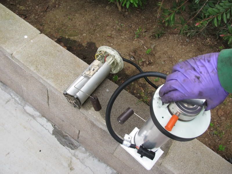
Open pump hole:
7. Installing New Pump
- Connect the blue plastic clip to the new fuel pump outlet. Once again, make sure the old black gasket is removed and the new one is on. The pump assembly is a self adjusting pump, so it's spring loaded. When you drop it in the hole, you will want to hold it down as it will want to spring back up. Make sure that the black gasket is not catching on the edges and is smoothly sealed all around. Go ahead and thread the plastic white ridged holder piece back on and tighten down a good amount... and your all done! Well not quite but your only going downhill from this point as everything has already been affiliated with.
Dropping new pump:
So from here just repeat all the steps backwards and you've installed your new fuel pump assembly. A key word of advice is for those with the towing package... go ahead and fire it up before you put the towing bracket and fuel tank guard on to check for any leaks. If no leaks and it runs than go ahead and continue on as your almost there!


