Wojtek90, did you recently replace the alternator with an aftermarket unit? I did, and immediately ran into alternator/ECM communications issues resulting in good charging only after the first 1, 2, 3,4 starts after battery-disconnection. It seems random how many I get. Others on JF with the 3.0l CRD OM642 diesel engine have observed similar behaviour after reman or aftermarket alternator installs.
The single-wire to ECU is a digital "LIN-bus" protocol wire. I dug deep enough to find chip-level regulator information and there are multiple variants of the LIN-Bus protocol and that may be the source of these issues. I still have a sticky U1132 bad-comms fault, but think I need to address it by getting the right regulator on the back of a "guaranteed to fit" alternator.
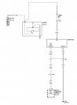
I checked the continuity of my "field wire" (actually LIN-Bus), which was good, and have the following notes left in my cellphone:
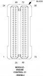
"PCM Connector C2 Pin 19 is the field wire, BR/DG (brown/dark-green) C104 Cable K125 to C104 pin 12, then C102 pin 2" Whatever that means :frown2: I think that was a trace from ECU to alternator.
I will see if I can find the wiring diagrams from which I was working at the time.
Meanwhile, anyone reading this thread know where I can get an alternator splash guard?
I know this is an OLD thread, but I am having nearly the exact same issue! Having a lot of trouble finding others with this issue, but this one sounds really similar! My story:
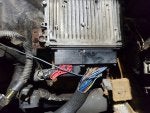
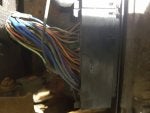
Battery light came on while driving. Every day driver, no issues until this. Voltage was draining, ended up having to get a tow home. Replaced alternator (PIA). Seemed fine for about 20 miles, then light came back on. Battery was not charging (tested voltage while running at battery terminals, LOW voltage, like 7). Thought maybe bad alternator from parts store (reman), so bought another (new), replaced AGAIN. Seemed ok, then battery light came back on after about 65 miles. Unhooking the field generator wire (single small wire that runs to "regulator" on alternator) and plugging it back in seemed to work. I got really good at getting to that wire, and drove it like this for a couple weeks, every 30-100 miles having to unhook and re-connect that wire every time the battery light came on. I installed a voltage meter next to the steering column so I could monitor voltage from inside while driving (they neglected to include a gauge on the dash, grr), so was able to verify that indeed, the battery was not getting voltage from the alternator when the battery light came on. All signs pointed to bad ECM/PCM, so I shelled out about $900 USD for the ONLY one I could find in North America. Seller assures it's good. They flashed it to my VIN, and a few days later, it arrives. I go to swap it out. Now I have the red lightning bolt of death, several codes that didn't exist before, and the Jeep now won't start AT ALL. Swapping the new back for the old PCM changes nothing. Gave up. Left sitting for a bit, battery was totally dead. Two days on trickle charger, and battery (1.5 years old) now won't hold a charge. Replaced with new battery, reading 12.7V, and still same issues. No start. I can't locate any loose, corroded or shorted wiring, though trying to trace all these lines from the harness is what led me to this post. I have searched hi and lo for ANY info on this topic over the last couple months, and this is the only post that seems to replicate what I have going on. Sorry for the novel, but REALLY hoping I can figure this out! It was driving fine, other than the battery no charge issue, and now it won't start at all, but nothing changed other than unplugging and plugging in a new PCM. All connectors look clean and straight, so I have no idea what the issue is...