

I know most of the jeep forum hate ABS but I like to have stuff thats supposed to work working. This project has been lurking for a long time and I knocked it out finally. I needed the ABS to work because when I rip the steering and suspension out to replace them{brakes included} I need to be able to use the DRB to bleed the brakes if I get air in the HCU. I had pulled a CAB out of a junkyard ahead of time and resoldered the motor connections on the board as in this video.
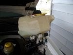
First as always disconnect the negative battery terminal. Pull the washer tank and tie it out of the way,2 10mm screws. Pull the airbox,3 13mm screws. This will give you room.
![]()
Pull the three nuts that hold the HCU brackett down. The lower stud has two nuts on it. The first holds on the steering box cover,the second one below that holds on the lower leg of the brackett.
![]()
![]()
![]()
Pull the tab release handle on the main CAB connector towards the firewall. This will unlock the connector and allow you to pull the connector straight up.You may to wiggle it a bit but don't get carried away. It has small pins it is not unlike the pcm pins and too much force will result in loose connections. Also, you may have to use a small screwdriver to gently pry that release handle out all the way. In the upper right hand corner you can see the HCU motor connections. Squeeze the sides of the connector and pull up.
![]()
The harness is held on to the body by two of these. Squeeze the ends together and pull them out of the body holes. This will allow you to get the harness somewhat out of your way.
![]()
At first I tried to take the 4 4mm screws out that attach the CAB to the HCU without releasing the CAB from the HCU brackett. With a 1/4 drive socket wrench I got 3 of them out.The right rear one was impossible for me to get.Its easier to remove the 3 13mm screws that hold the HCU to its brackett loose, cause it gives you wiggle room to get to that 4th screw. The lines have some spring to them but don't get carried away. Remove the brackett before trying the 4th screw. Tie off the HCU/CAB to support it so its weight doesn't rest on the lines.
![]()
![]()
Pic of three of the 4mm screws that hold on the CAB to the HCU. Do yourself a favor and put a piece of tape over the hole at the bottom of the coil tower. Guess where the 4th screw went? Luckily I had an extra.
![]()
It was pretty nasty in there so I broke out the purple power and degreased and painted after masking some stuff off.
![]()
Put it all back in and in the next post I'll show you the result.
First as always disconnect the negative battery terminal. Pull the washer tank and tie it out of the way,2 10mm screws. Pull the airbox,3 13mm screws. This will give you room.
Pull the three nuts that hold the HCU brackett down. The lower stud has two nuts on it. The first holds on the steering box cover,the second one below that holds on the lower leg of the brackett.


Pull the tab release handle on the main CAB connector towards the firewall. This will unlock the connector and allow you to pull the connector straight up.You may to wiggle it a bit but don't get carried away. It has small pins it is not unlike the pcm pins and too much force will result in loose connections. Also, you may have to use a small screwdriver to gently pry that release handle out all the way. In the upper right hand corner you can see the HCU motor connections. Squeeze the sides of the connector and pull up.

The harness is held on to the body by two of these. Squeeze the ends together and pull them out of the body holes. This will allow you to get the harness somewhat out of your way.

At first I tried to take the 4 4mm screws out that attach the CAB to the HCU without releasing the CAB from the HCU brackett. With a 1/4 drive socket wrench I got 3 of them out.The right rear one was impossible for me to get.Its easier to remove the 3 13mm screws that hold the HCU to its brackett loose, cause it gives you wiggle room to get to that 4th screw. The lines have some spring to them but don't get carried away. Remove the brackett before trying the 4th screw. Tie off the HCU/CAB to support it so its weight doesn't rest on the lines.


Pic of three of the 4mm screws that hold on the CAB to the HCU. Do yourself a favor and put a piece of tape over the hole at the bottom of the coil tower. Guess where the 4th screw went? Luckily I had an extra.

It was pretty nasty in there so I broke out the purple power and degreased and painted after masking some stuff off.

Put it all back in and in the next post I'll show you the result.


