The automatic transmission is operated with the help of a shift lever assembly (SLA) located in the floor console. There are six positions to which the selection lever can be shifted: Park, Reverse, Neutral, Drive, Manual Second, Manual Low. The selector lever positions ""P"", ""R"", ""N"" ""D"" ""2"" and ""1"" are transmitted by a shift cable to the selector shaft in the transmission, indication in cluster.
•Park (P)
•Reverse (R)
•Neutral (N)
•Drive (D)
•Manual second (2)
•Manual low (1)
The SLA is comprised of the following functions.
Key lock
Depending on the selector lever position, the ignition cylinder is locked/unlocked, i.e., the ignition key can be removed only if the selector lever is in position "P", and the shift lever can be moved out of "P" only after the key has been turned clockwise from LOCK (1) position. A park lock cable is used to perform this functions.
Park lock
The selector lever is not released from postion "P" until the brake pedal has been applied and the ignition key is in ON (3) position. Shift lock is controlled by the brake light switch in conjunction with a locking solenoid in the SLA. As soon as the brake pedal is applied, the locking solenoid is energized and retracted to unlock the selector lever. If the selector lever cannot be moved out of position "P" due to a malfunction, the shift lock function can be overriden.
ADJUSTMENTS - park lock The interlock cable connects the lock housing and the ATX shifter. The shifter is locked until the key cylinder is rotated clockwise from the LOCK (1) position. Once the key cylinder is rotated out of LOCK (1), the shifter may be moved from Park. As the shifter moved from Park, the interlock cable is held at a position that prevents key removal.
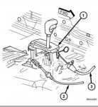
1. Remove floor console as necessary for access to the park-interlock cable.
2. Make sure the shifer is in PARK position.
3. Un-snap the cable end fitting from shifter base reaction bracket.
4. Attempt to take out the key from ignition cylinder moving the core cable fore/aft.
5. With the key removed from cylinder, un-snap the locking tab from cable end-fitting.
6. Slide back in the cable end-fitting onto shifter base reaction bracket.
7. Push in the locking tab until fully seated - the top surface must be under flash relatively to cylinder end-fitting and both sides snapped over the locking features.
8. Verify proper operation.
9. Install the floor console.