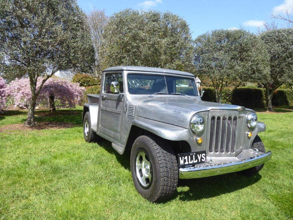
Jeep Enthusiast Forums banner

GrandWillys Project

205K views 1.3K replies 71 participants last post by  Gojeep  
#1 ·
This project is about combining a 2008 WH/WK Grand Cherokee 5.7 HEMI with a 1948 Willys Pickup.

I have had a thread on other forums going for the last 6 years and have been often asked to post it here as well. As I just got my own domain and server space, I have to repost every picture I had so seems a good time to post it here as well.
Hope those that have followed it elsewhere don't mind but have found site activity or some of the other forums it is on has dropped off a lot in the last couple of years. This one being for more than one model looks far more active. :smile2:
 
#1,051 ·
I have just started building a hard tonneau cover for it that will hinge up and be supported on gas struts.
Will also be lockable so my camping gear in the bed is safe when parked.
Been doing a few refinement jobs as well as don't want to do anything like that after paint.
 
#1,053 ·
Congratulations, Marcus. That is truely a beautiful and unique vehicle you have built.

I have really enjoyed the journey. Thanks for bringing us along for the ride.
 
#1,058 ·
Image

Addressing some of the things that could be improved. I was worried when I first made my fuel filler that it could be a slow fill because it first went over the top of the tank with only a little slope before dropping down to the filler port. Tested it with a jerry can it it was fine, however the first time I filled it at the pump it was a different story. It kept shutting off as any spit back made it stop. Only turning the nozzle upside down would allow it to run at half speed but then spill out every where once full! Thought if I had the drop first and then run into the tank might help. No difference at all, even after disconnecting the vent line from the charcoal canister.

Image

So picked up another filler from the same model donor Jeep to see if extra height would help. Wanted to test it first before making anything permanent. So drove to the service station like this and it worked perfectly.

Image

I straightened out the vent line and added a new bend where it would go under the floor. Used some bigger stainless tubing to replace the stock one with the bends in it and added a elbow at the bottom.

Image

The top of the old setup is now the bottom of the new one. Gives you an idea of how much extra 'head' it will have, 400mm/16" extra. The tube coming down from the holder is in case any spillage occurs, it will drain out below the floor level and not inside the bed.

Image

While I was filling up I made a quick tracing of the fuel nozzle so I could make sure it would work well enough. Also that it will still fit once I have a hard tonneau cover hinging over it.

Image

So I got it tucked right hard in the corner and takes little floor space. Running it in from the outside took up a lot more room as it needs a fairly soft radius for the nozzle to still go in far enough.

Image

The drop in the side piece makes it comfortable to open and close the cap.

Image

I had a piece of old stainless that had been heated in the middle and was all warped. Managed to wheel out the shrinkage from the heat and make it good enough to make a shield from. The tabs are for the mounting screws.

Image

I made it wrap around the top and screwed in so it can be easily removed if needed.

Image

The curved part was first wheeled as far as I could get it before bending it the rest of the way over some pipe.
 
#1,059 ·
Sorry for all the pictures but often get asked how I can make my welds 'disappear'. Also thought I would show you can do this with a MIG which I often use on small patches like this.

Image

Now I am left with a hole in the side of the bed! So glad I found this out before paint.

Image

I had to drill out the spot welds I had used to fit the reinforcement ring behind the hole for the filler neck mounting screws. So now I have 10 holes to fill.

Image

Clamped some copper behind the holes which the weld won't stick too. Also helps draw in heat and means I don't have to grind the backside which is hard to get to.

Image

I used a single good hot tack with the mig to fill them. No cooling the weld as don't want to harden the surface making planishing difficult.

Image

Ground down the welds to a razor blade thickness proud of the surface. This gives me a little extra to flatten hammer on dolly to stretch the welds after shrinking from the heat/cool cycle. Important to get it back flat again before moving on.

Image

I am just using this dolly on the small crown side and this hammer to centre the hits directly over each weld spot.

Image

I do this differently to most you see on shows and youtube by tack staking the patch between the ground down tacks. Each new tack is placed while the one before is still orange in colour. If the last tack cools, you must grind it down to almost flush before adding another tack next to it. Never use air or water to cool as it makes the surface brittle. If you tack and quickly cool, you cannot planish the weld for this reason.

Image

I still move from one side to the other to tack stack between the tacks holding the patch in place.

Image

Because space is limited, I am knocking down the weld with what once was a 9" cut-off disc! I used it in my 9" grinder until it was 5" in size. Then use it in my 5" grinder until it is about 2.5" in size. Then it goes on my die grinder. Only use it on its edge like shown and not on its side like a grinding disc.

Image

There is a bit of a dip off to the side where it has been welded. I still will not raise that area as I know it was not there before welding up all the holes. It tells me more stretch is needed at the weld site.

Image

Keep checking in all directions and only still hitting where it was welded. If it starts to actually get worse, you have stretched too far and need to shrink it down a fraction using a shrinking disc.

Image

Notice the imperfections left from the welding in the surface.

Image

I get rid of them by carefully tacking lightly over the imperfections. This means grinding them down once again and stretching to get back to flat.

Image

The very last part of the almost flat ground welds is done with a flap disc and then followed up with a strip disc.

Image

Using the strip disc can also cause a little shrinking as well. Sometimes good to put a little tension in the panel but might need a slight hammer on dolly work as well.

Image

Holes be gone! Can barely tell they were ever there now.
 
This post has been deleted
#1,061 ·
Still working on little details as they show themselves. Been a lot less than I expected to be honest.

Image

To help slow the, "you got a LS in that?", questions, I added a small HEMI badge.

Image

We came up with putting it here on the guard away from the WILLYS pressing as it clashed a bit there and made it a bit busy. Funny thing is that the Chevy guys are even more impressed that it has a HEMI rather than a LS!

Image

Another thing I did was swap out the stock KK Cherokee rear coils in the rear for some stock WH Grand Cherokee ones the same as the donor. I actually used well worn ones from a wreaking yard as they sat an inch lower than my near original donor ones. The ride is so much better in the rear now and matches the front end. It also added another inch of 'hotrod rake' to it. ;)

Image

I had been looking for mirrors that sat out a bit further to help with the wedge shape of the cab, but found nothing I liked more than what I already had. So thought why not widen the ones I already had. First to test the idea I whittled down some 50mm square stock pine and put it in my metal lathe. Used the parting tool to try out some shapes.

Image

This is the shorter of the two I made and quite like the proportions. It is the same height as the diametre of the base.

Image

Was not as keen on the longer version and worried it might vibrate more too.

Image

Next test was to make one out of some scrap aluminium bar stock that I picked up at the scrap yard the last time I was there.

Image

Happy with the shape and size of it. It is not just a straight taper as wanted to mimic the jam nut and make it look less like it was done on a lathe.

Image

The aluminium was too soft to use and scratched easily. So had some solid 40mm 316 stainless bar stock to make some from.

Image

I machined both ends of the bar so could easily duplicate the settings and make them identical.

Image

I went through the grades of sandpaper over it right up to 1200 grade which was the finest I had.

Image

Then onto the buffing wheels to give a better polish to it. Just wanted to match the mirror arm in sheen.

Image

The centre was bored and then tapped 16x1.5mm to match that of the mirror and the mount I already had inside the door. Then the fun part of parting each end off without it flying off somewhere at the end and damaging the polished surface. Did the old pencil inside the piece to hold it when nearing the end to catch it.

Image

Made some gaskets for it and threaded in a set screw. I used loctite to hold them in place with the hex socket inside the spacer. This allows me to tighten the piece to the door before the mirror gets screwed on.

Image

Think it looks fine fitted and can now see my rear wheel to help me reverse into the garage.

Image

Went for a Sunday drive and they are actually more stable than before with little to no vibration! The surface area of the mount is double of what it was before and there is less wind noise too as a bonus.
 
#1,062 ·
And it looks like the mirror was meant to be just like that. Nice work Marcus.

And by the way, I have a similar badge in a similar location on my Jeep. We are like brothers from opposite Hemispheres...

Image
 
#1,069 ·
Thanks mate.
Going to take it to a car show for the first time this Sunday in the little country town of Euroa.
Never been an entrant before so a new experience for me. Just going along to take part and don't expect it to generate much interest as mainly for car clubs and restored vehicles. Plenty of things to see and do regardless, so should be a good day out.
 
#1,070 ·
Image

Sunday coffee run.

Image

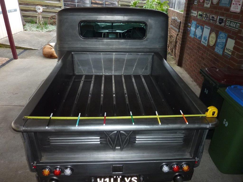
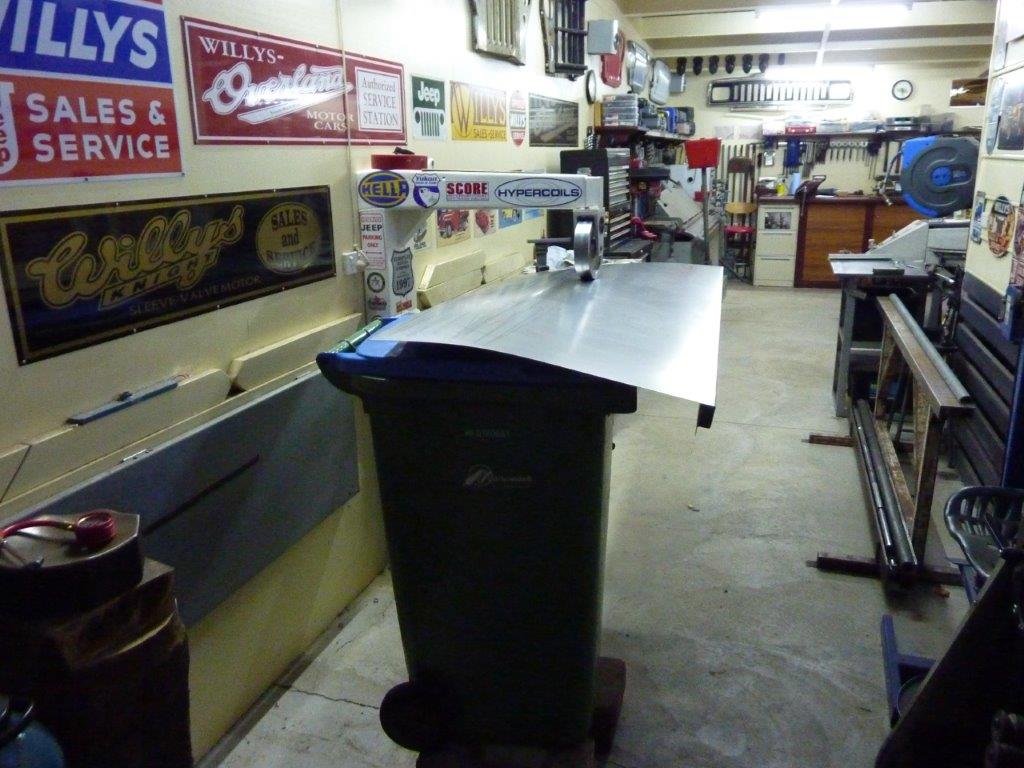
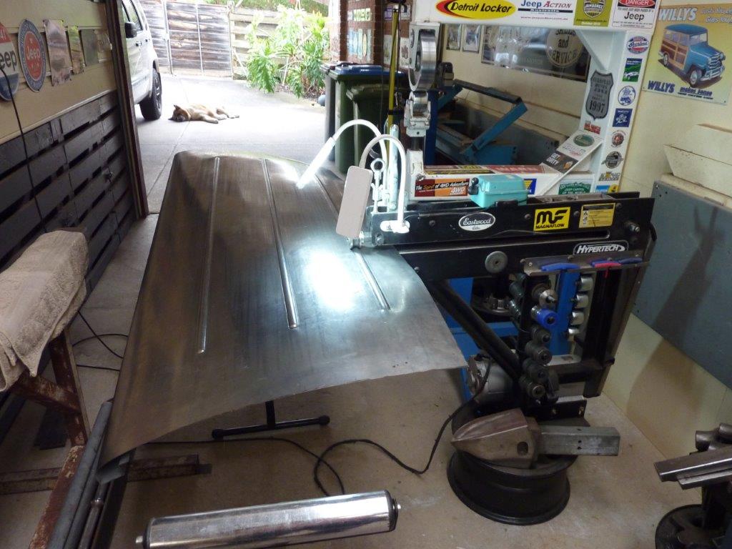
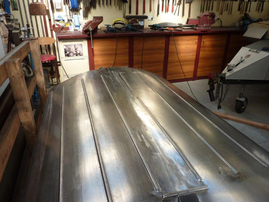
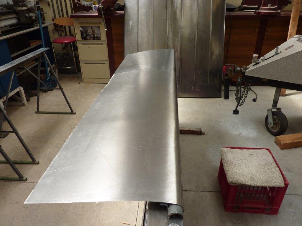
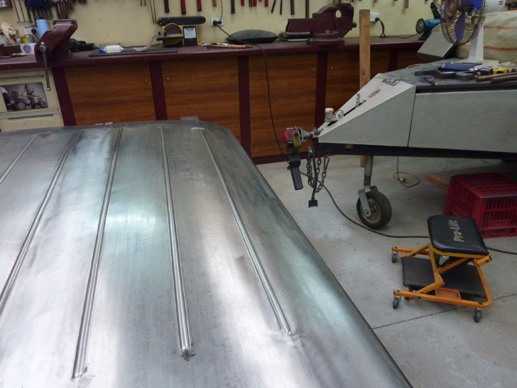
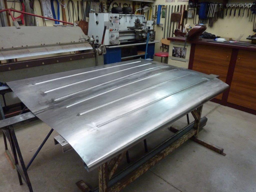
Last piece of the build to go, making the hard tonneau cover. Just visually looking at how many beads to run up the centre of the cover to stop fluttering at speed and also break up the large flat surface. The beads will be the same size as those on the cab and tailgate.

Image

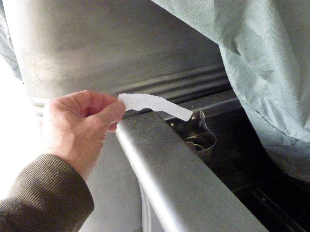
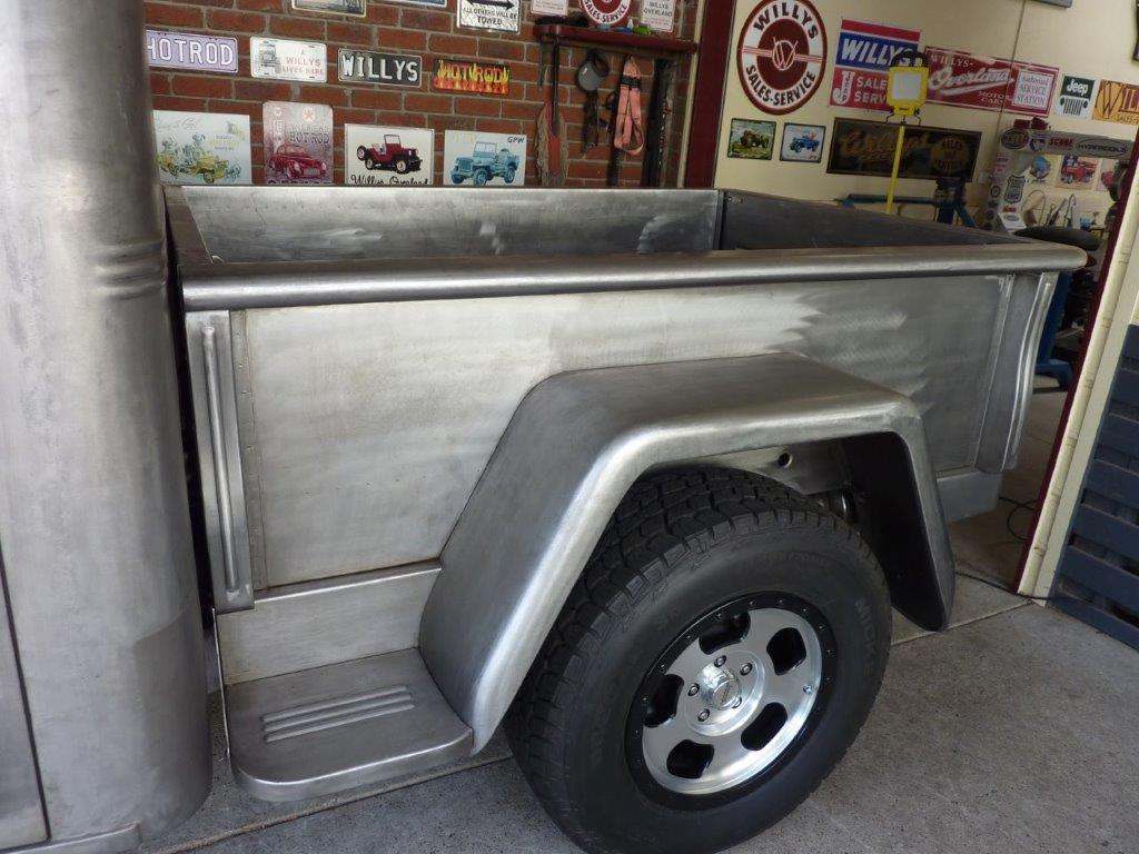
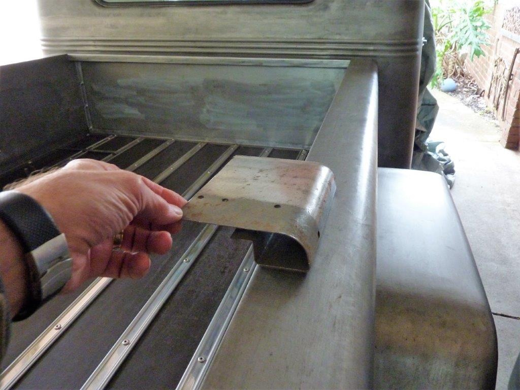
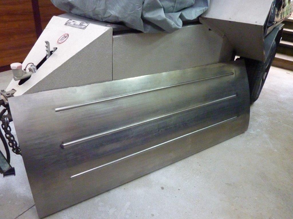
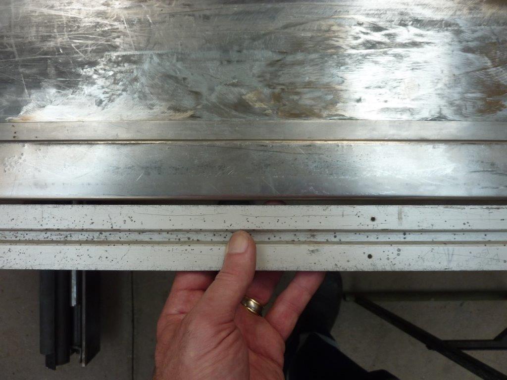
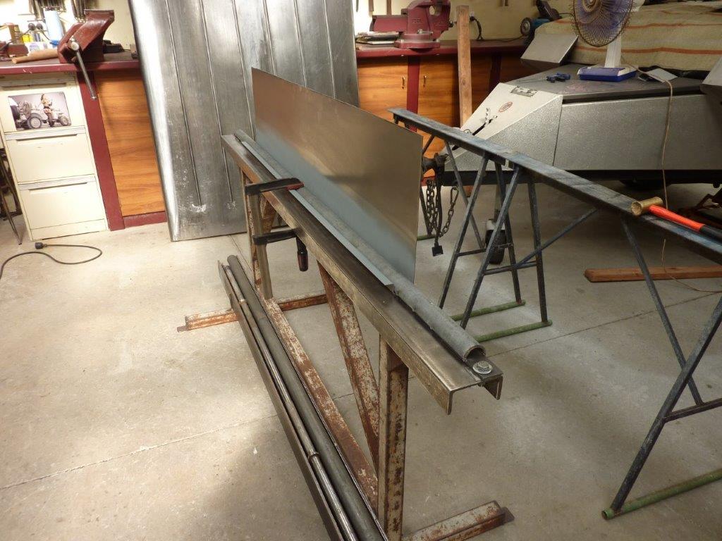
This is the shape I have come up with for the edges of the cover. Has the same radius as the bed sides and also gives me the height I need to fit over my camping fridge. The shape also gives me the strength I need to make a 'frameless' cover.

Image

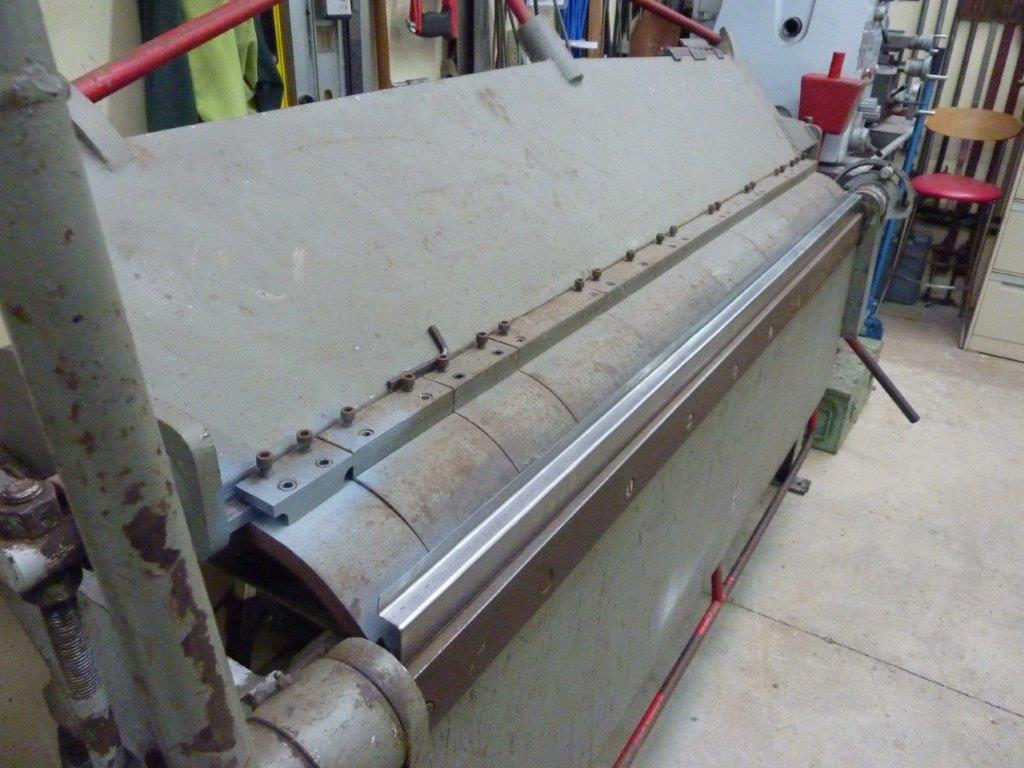
I used every millimetre of my 'new to me' folder. What used to take 20 minutes per fold by hand, now takes 20 seconds! :) I had to make sure I got the triple 'O' correct, (Order Of Operation), otherwise I could not have completed all the bends in the folder.

Image

The folds were planned out to give me the room I need for the half round form I will use later, as well as the amount of set back from the bed side top I wanted.

Image

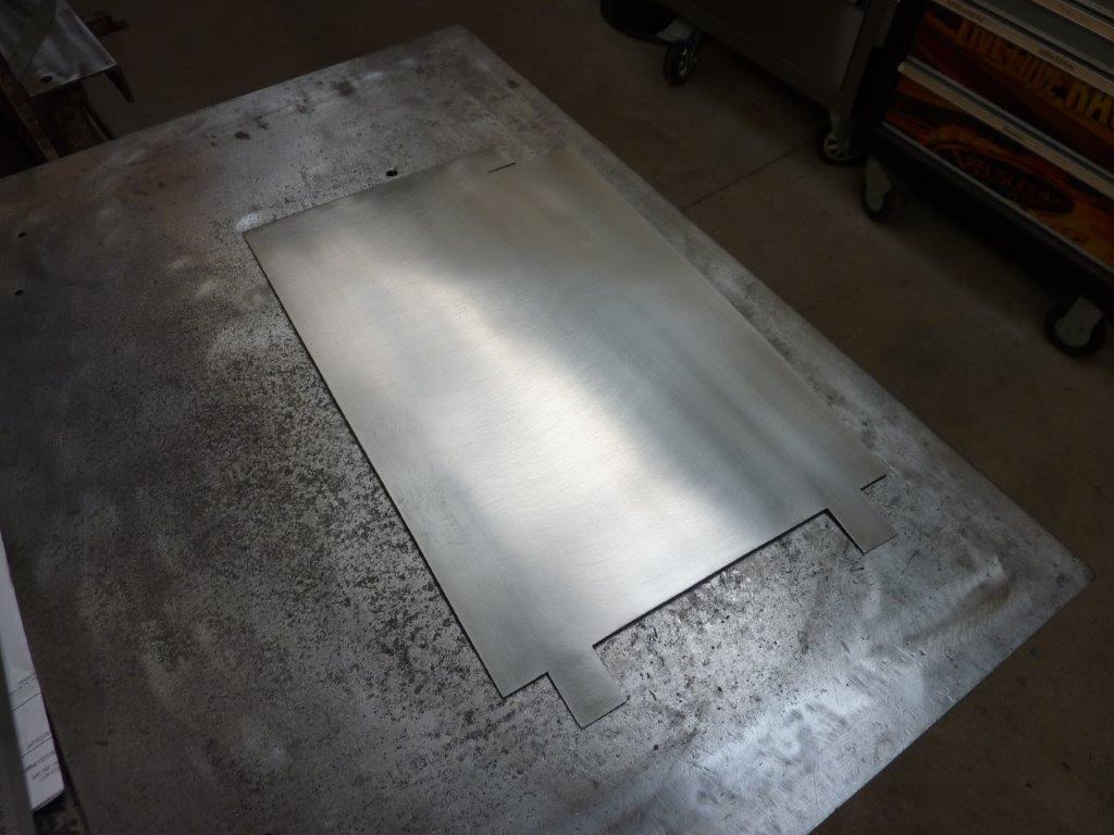
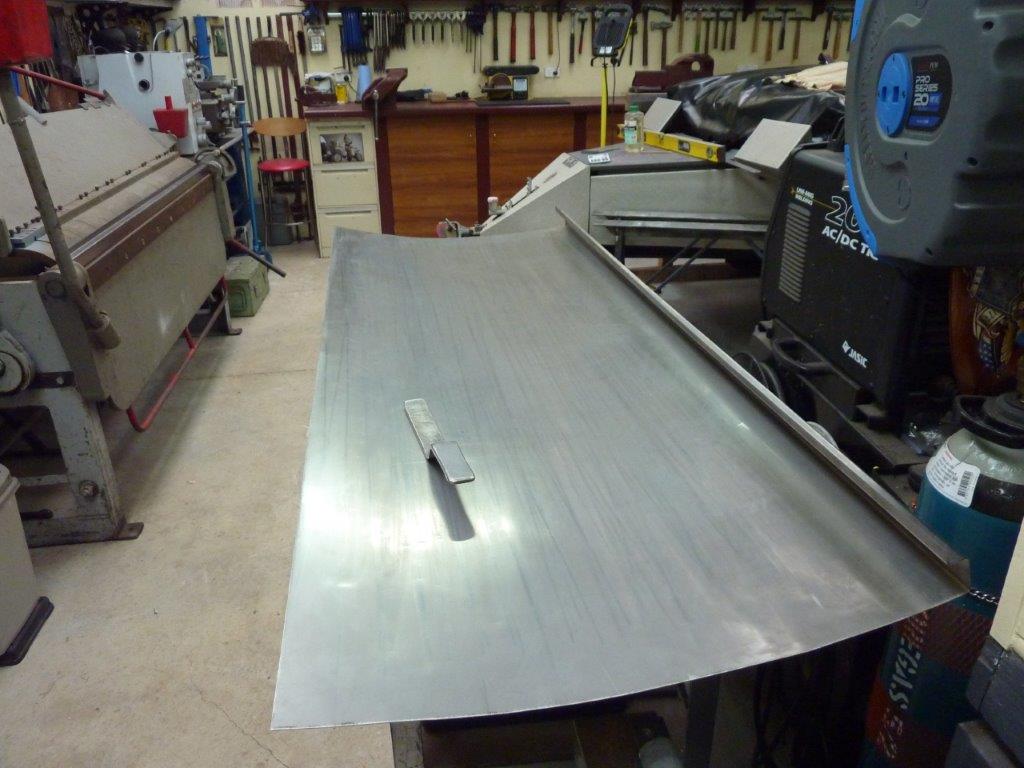
Now to put in a shallow crown in the half panel. I tried to do this by myself by having the panel supported on a couple of my rubbish bins. If you don't support it correctly, you will impart more bend with each pass than you want for a low crown.

Image

Unfortunately it didn't work out as well as I hoped and I created I lot of extra work for myself. I couldn't put in as many passes so then had to soften every line by hand to spread the crown out.

Image

So I waited until my wife could help me pass the sheet through the wheel. I was also able to use light pressure to fix the first panel some more, but you can still see how much smoother the far most panel is when done with the 2 of us from the start. I did manage to match the crown of both halves first go though!

Image

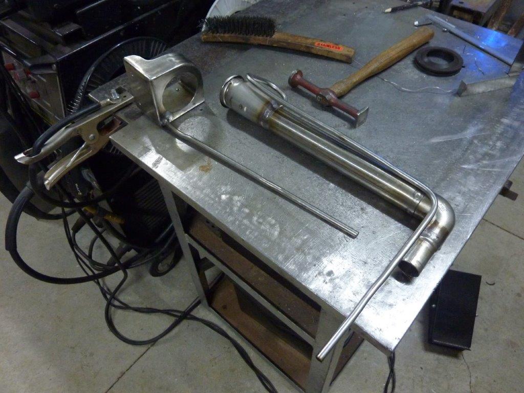
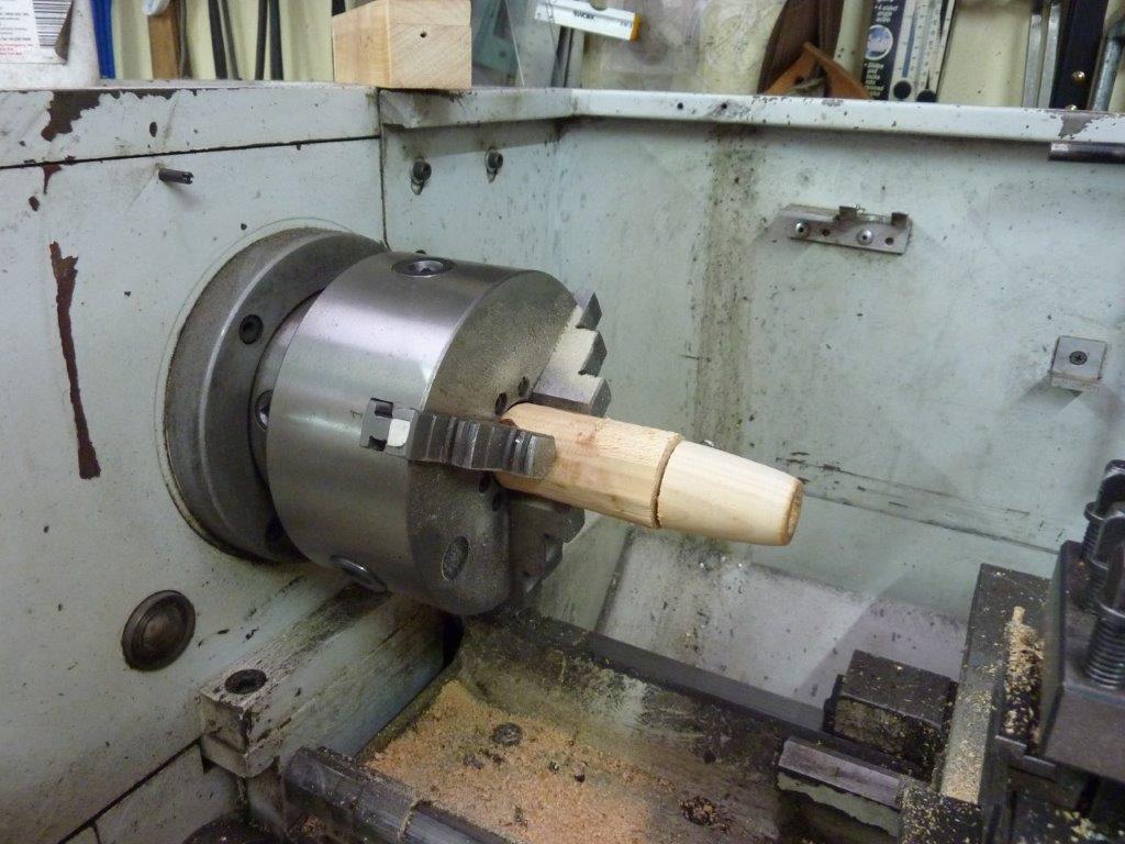
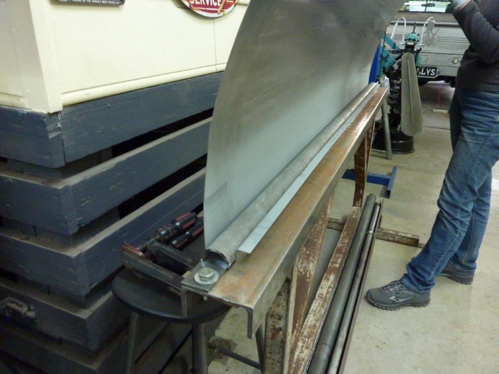
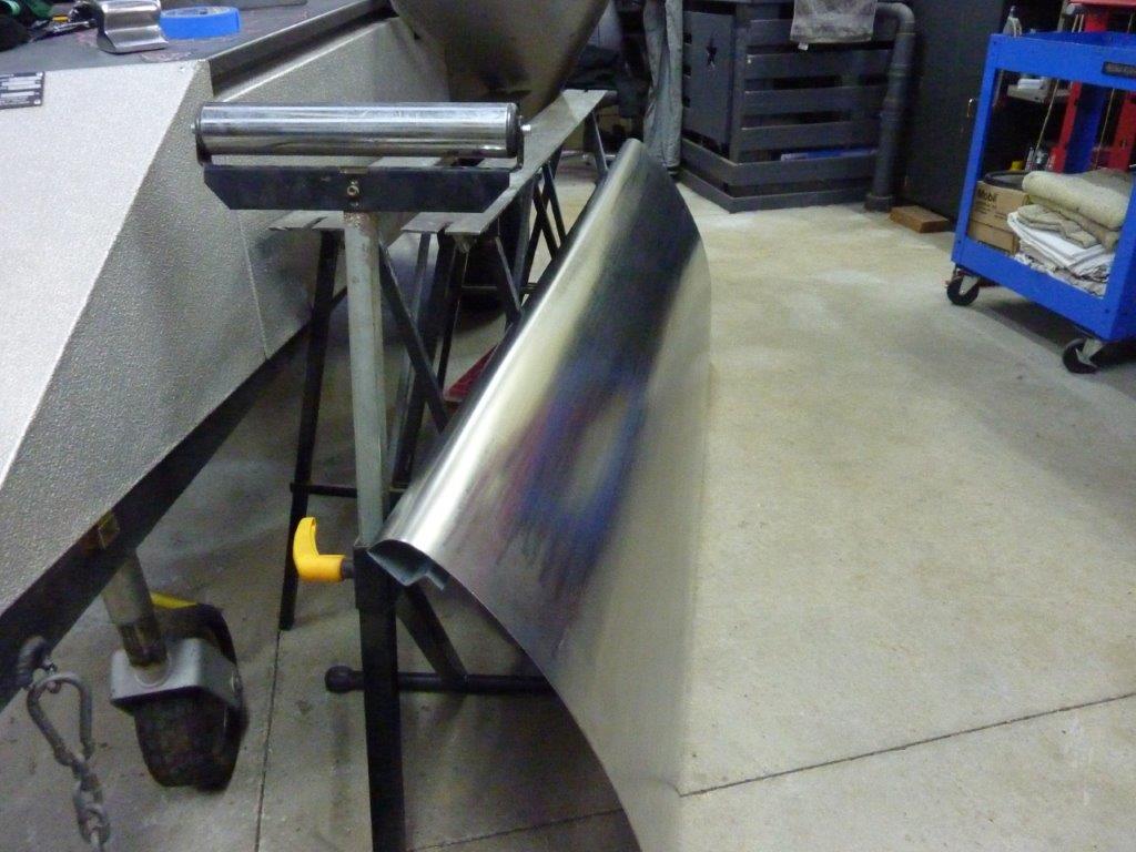
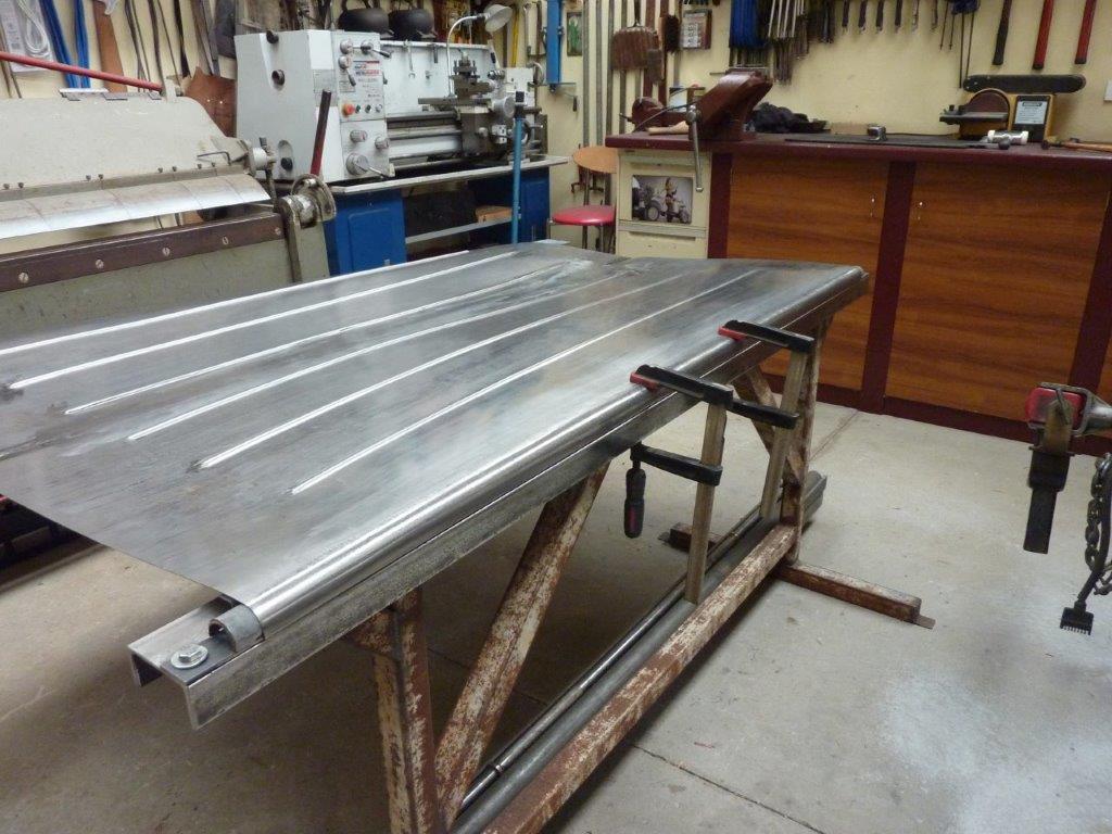
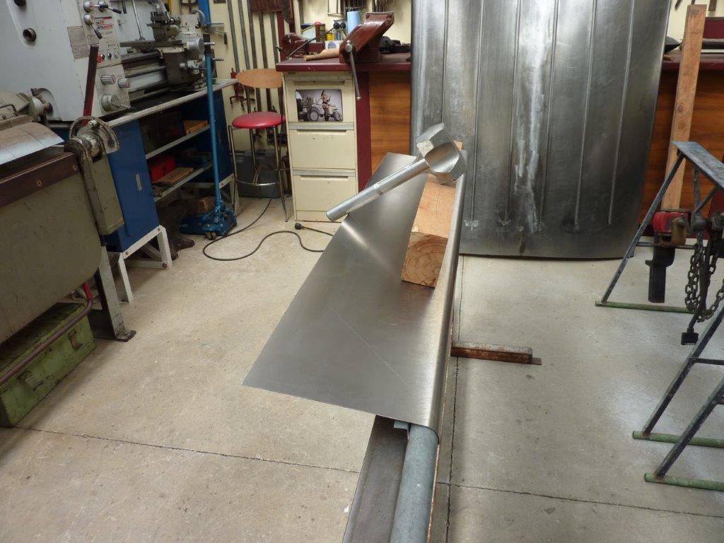
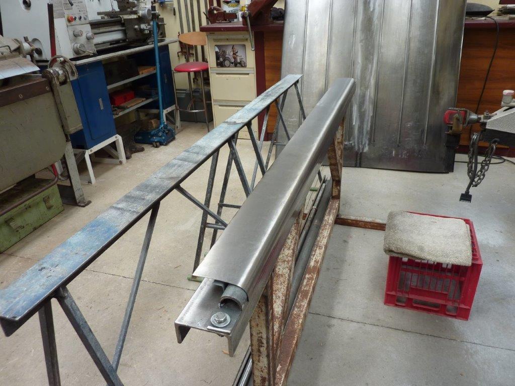
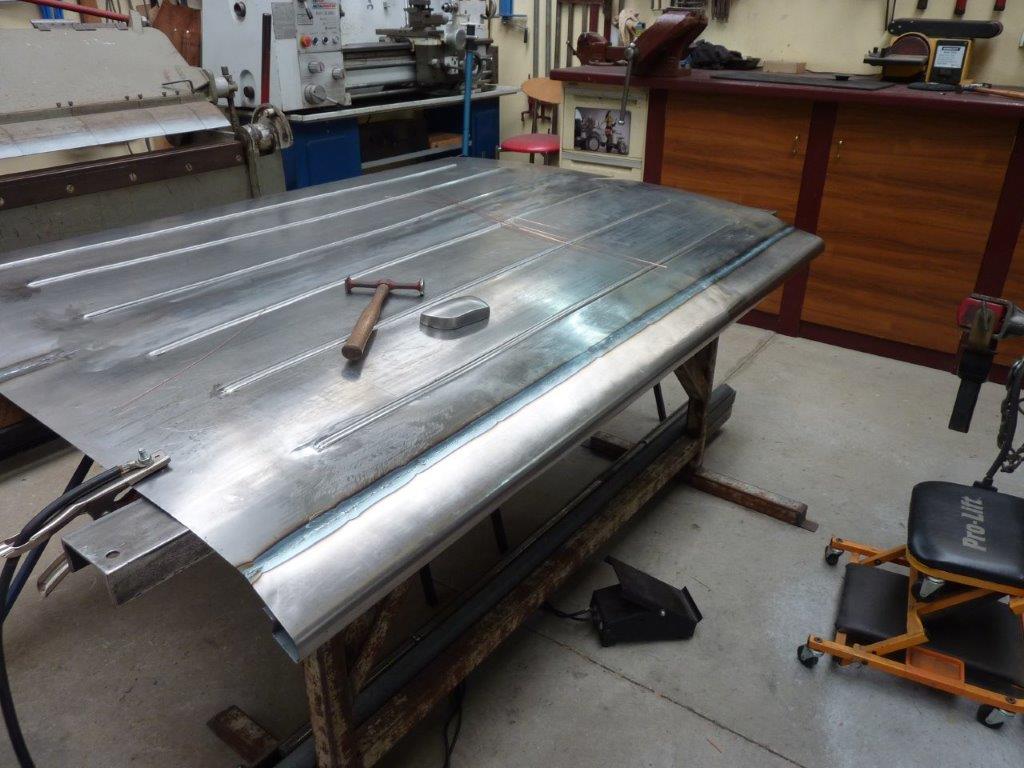
So this is the form I made by cutting a pipe in half and then tack welding it to some flat bar. I then placed the form inside the folded part of the panel and bolted it down to the stand.

Image

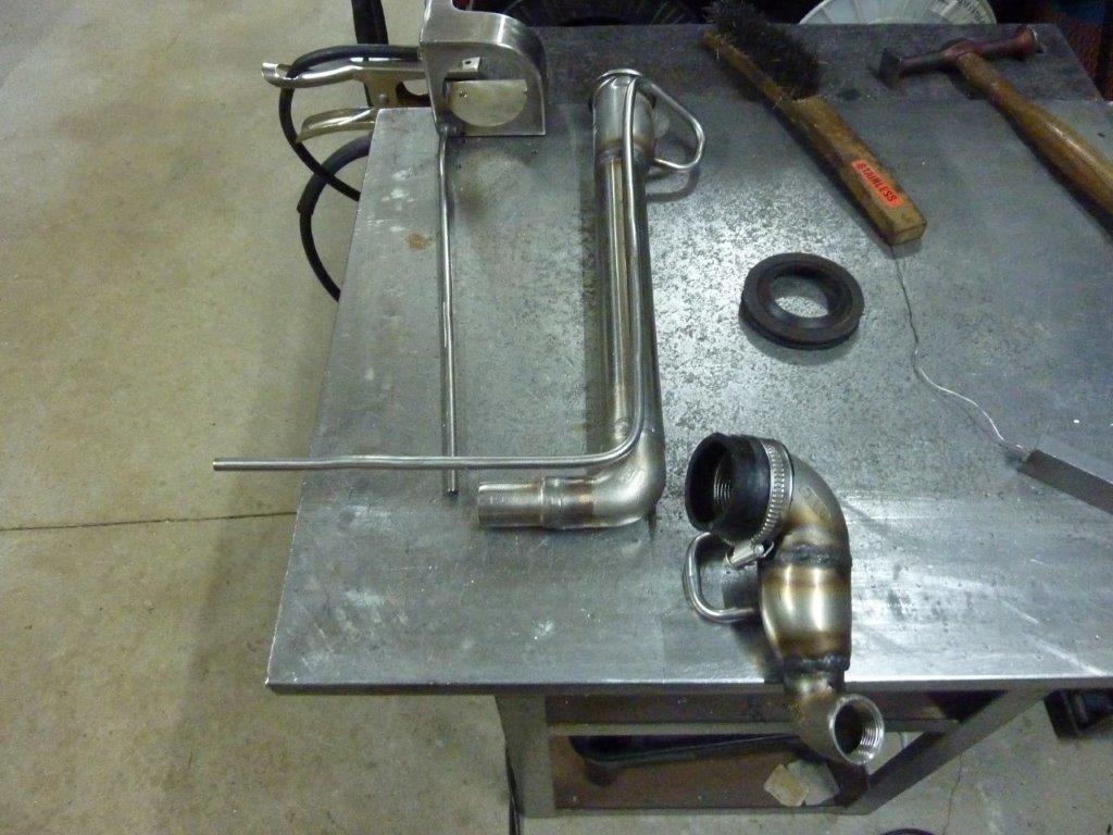
Then I just pulled it over by myself, (video to come), and finished the roll using the lead beating bat.

Image

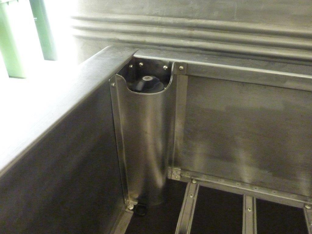
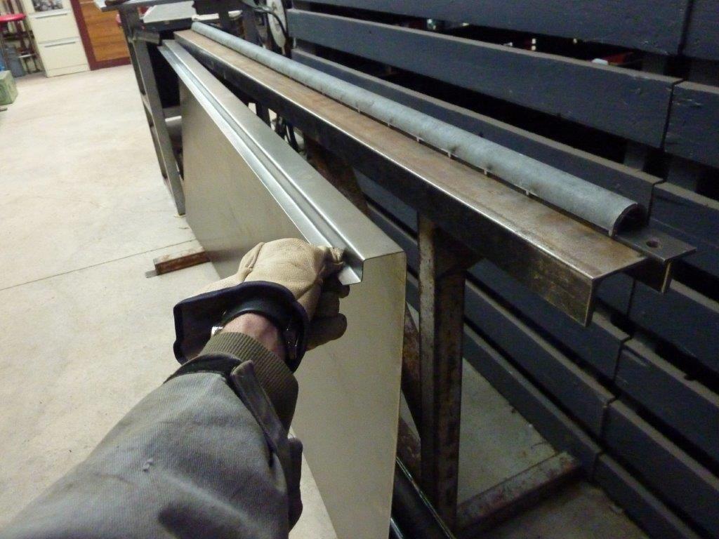
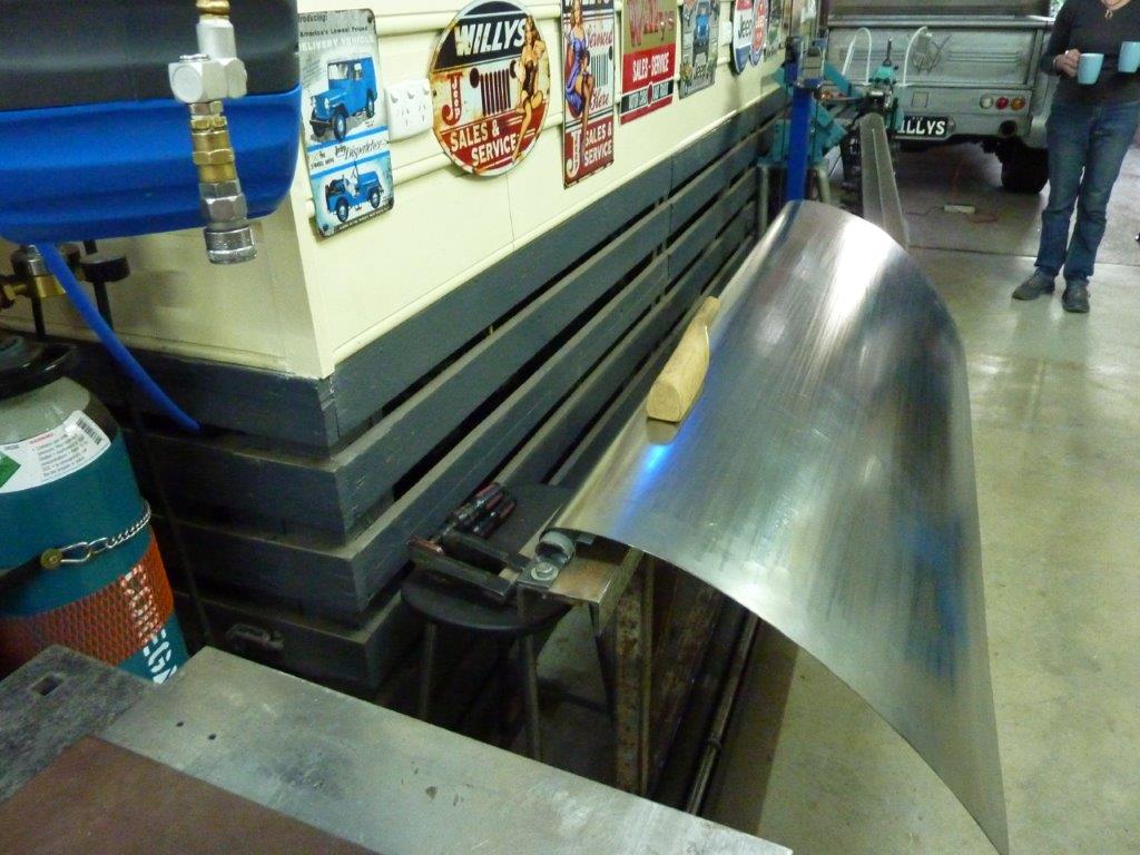
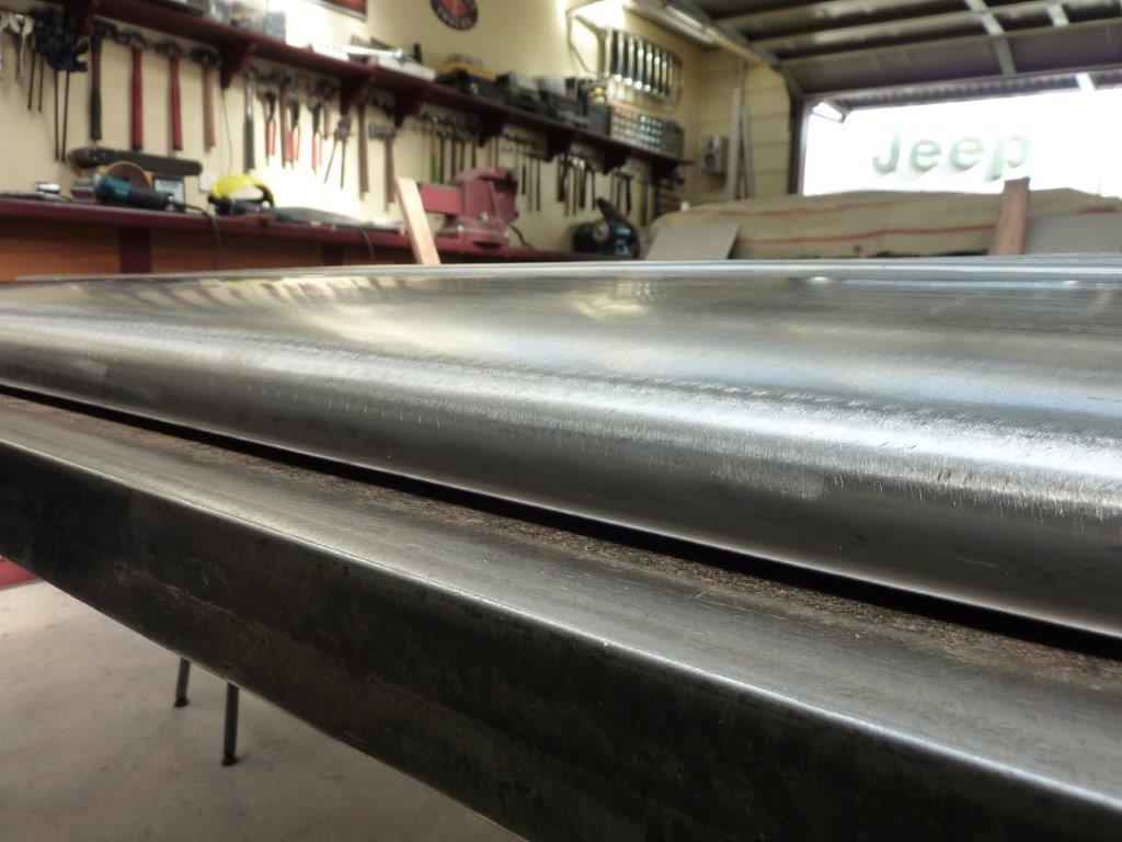
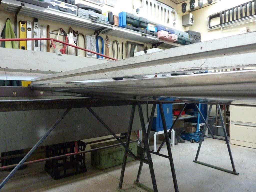
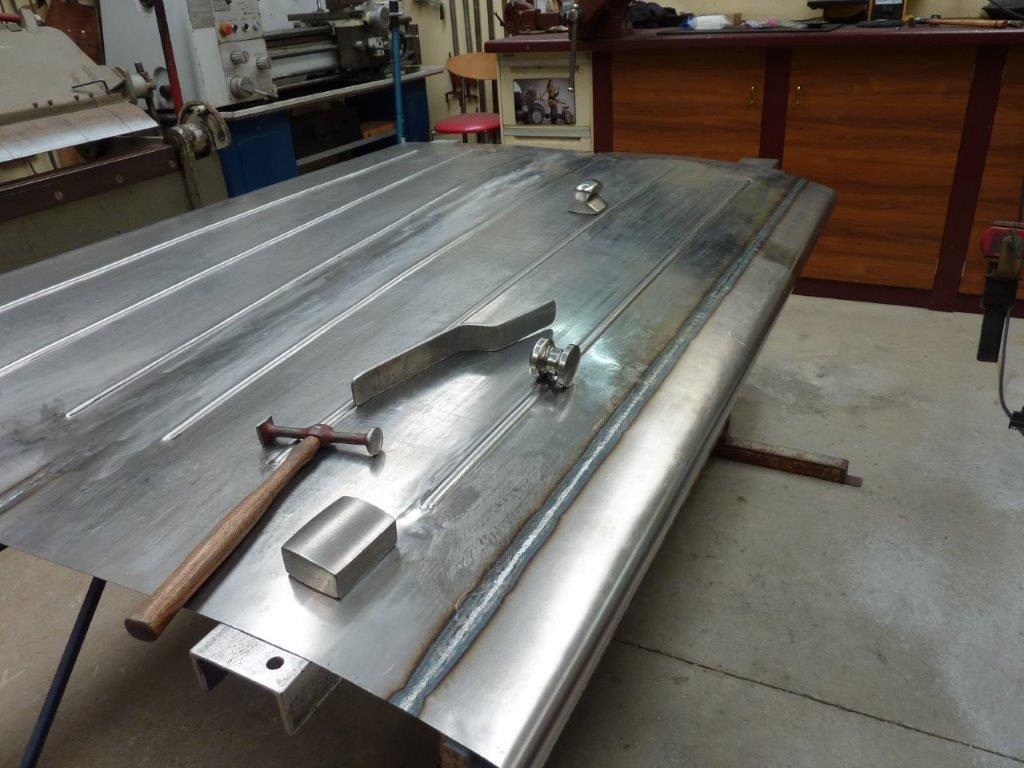
Here you can see the finished rounded edge. Now just have to repeat it for the other half of the cover which will be welded to this later.

Image

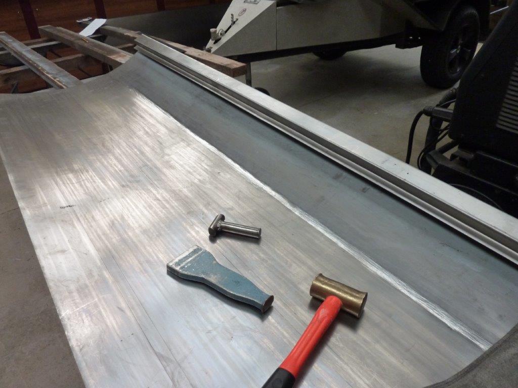
To create a bead you need extra material if the bead does not run right to the ends. Normally I do this by passing it through the English Wheel with a high crown anvil. But as I was on my own again, I did the stretching by belting the 'T' dolly along the marked area where the bead will be, directly over my steel bench. Then hit it some more with the chaser to make it a bit more even. You could just directly hammer the whole thing too, but do not go outside the bead area. I have never been able to pre-stretch too much for large beads like this.

Image

I had to do some extra machining to my 19mm-3/4" bead dies as they were not nesting properly. They need to be able to fit inside each other with only a material thickness left.

Image

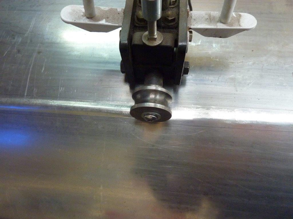
On the right of the roller going into the dies is the rough pre-stretched area, and on the left the first pass coming out. Can see how it is starting to smooth out already. I also ran guide lines each side of the outside of the top die to make it easier to follow accurately.

Image

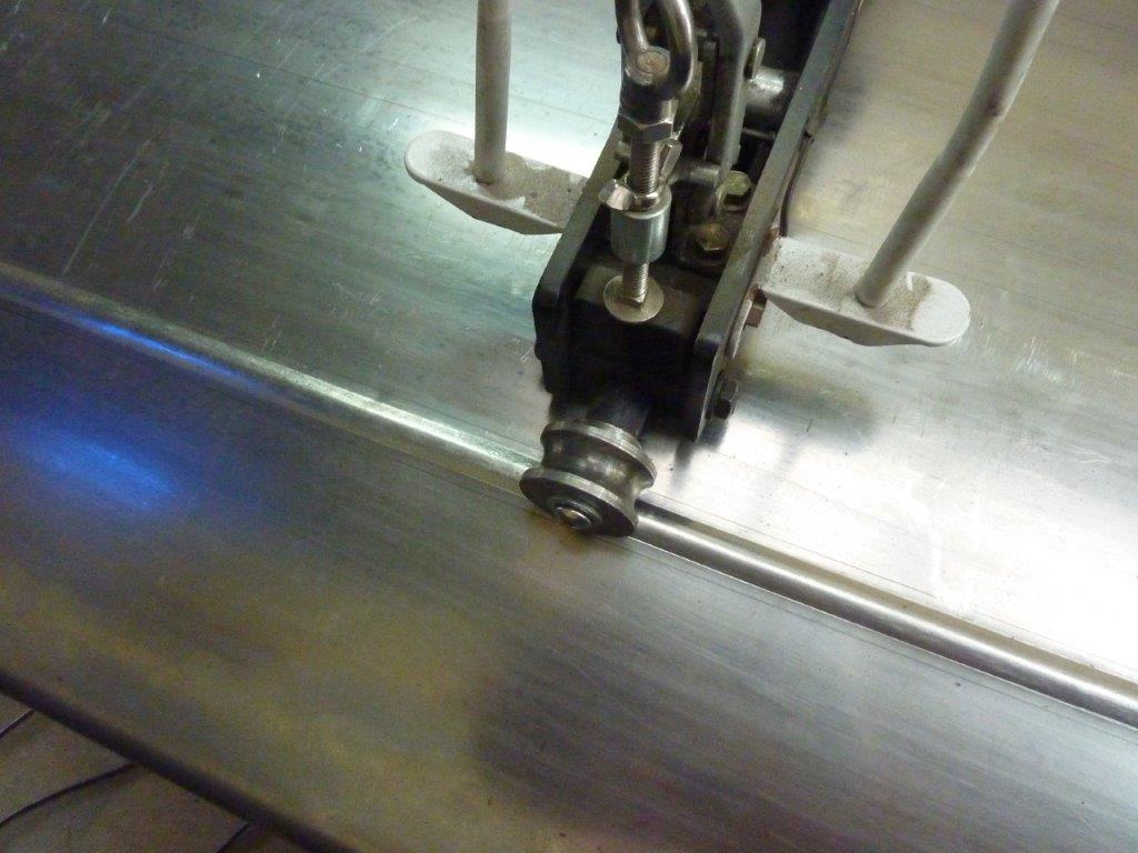
Increasing the pressure for the return pass, you can now see on the right how much better the bead is getting. I did around 7 passes in all to get it to full height.

Image

Rounded the end of the bead using a piece of notched pipe. There is still some pull down around the bead area showing it still didn't have enough pre-stretch, so will have to address that later.

Image

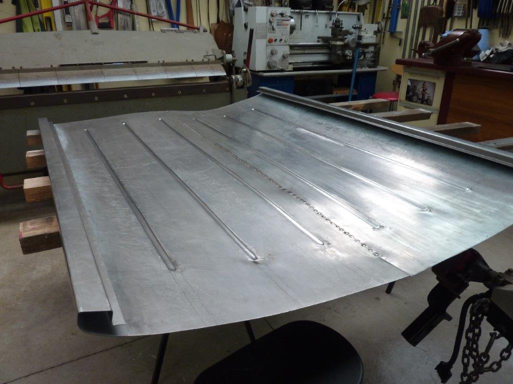
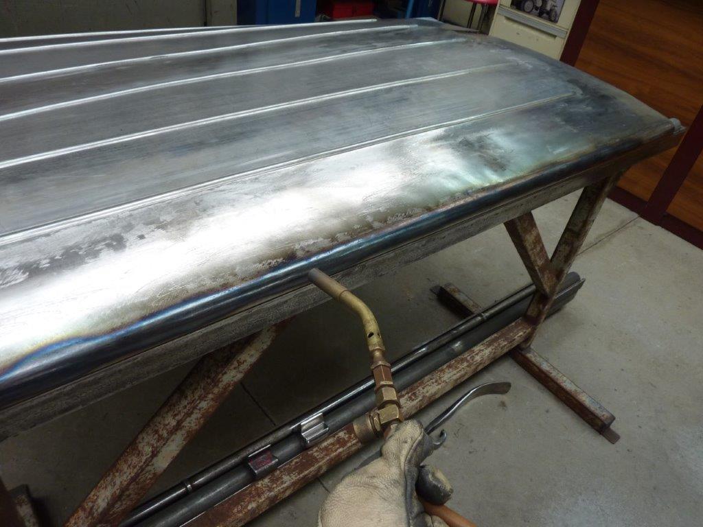
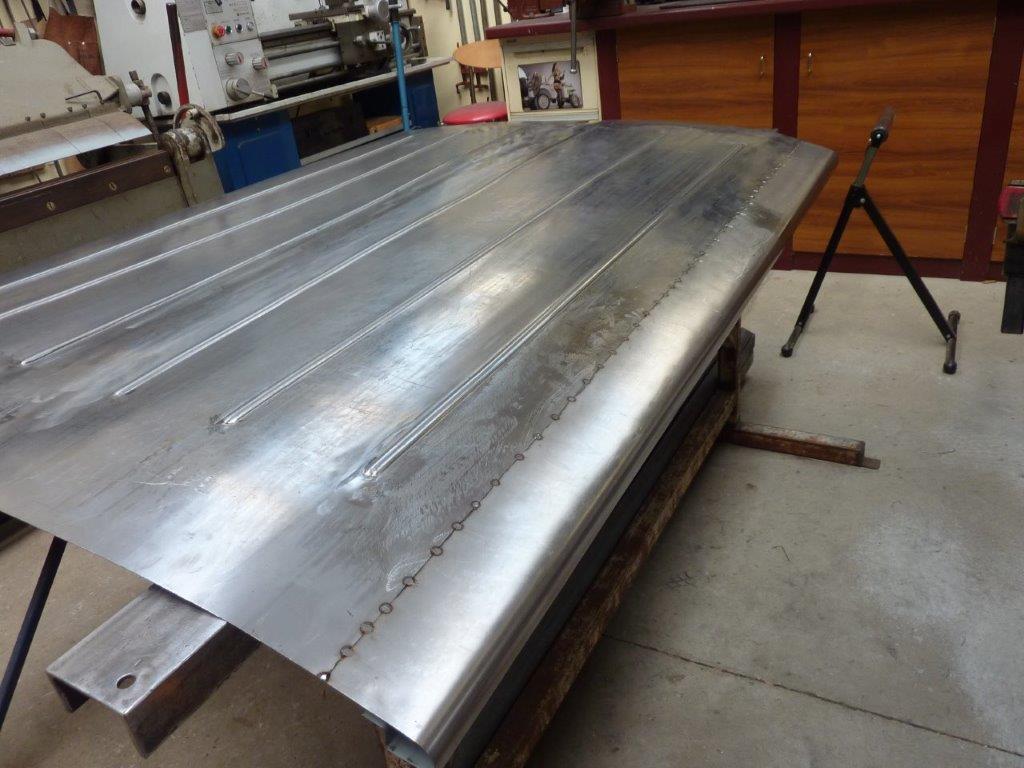
Last bead being done on this half of the tonneau cover.

Image

One half done, another half still to go.

Image

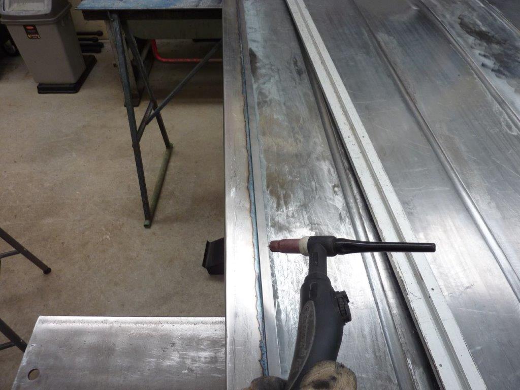
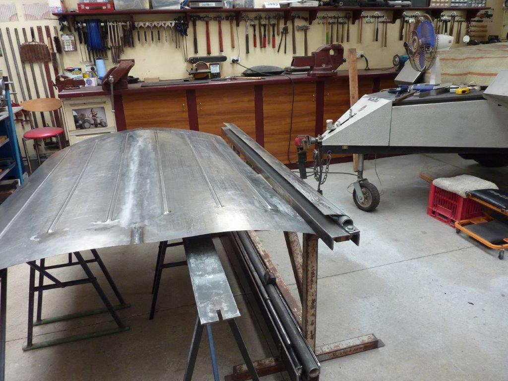
With both sides now done it was time to tack them together. See how uneven the metal is before I have stretched the tacks after welding. I will get it even before I start to TIG weld this all together. Some puckering at the end of the beads show more pre-stretch was needed. I'm not too concerned at this stage as I will be cutting part of the unfolded ends away to add the same rounded profile as the sides. Just couldn't be done all at once as tried to fold and roll on a test piece, but it was not possible.
 
#1,071 ·
Image

Came up with a sign for the Truck for when it is at an event. Wanted something that told what it was about at a casual glance, and not be put off by too much information. The QR codes I created goes to the website of the build and the YouTube playlist on it if people want to know more.

Image

Had it printed on some aluminium composite material so will last a while. Was able to use my wife's experience in making scientific posters for doing the layout for me.
 
#1,072 ·
Image

Getting the centre weld looking like this took twice as long as normal! Probably 12 hours all up from cutting, tacking together, welding, planishing, grinding, and sanding this 6 foot join. I couldn't reach into the centre with the dolly in one hand while seeing what my hammer was doing on the topside at the same time. I ended up balancing the dolly on a trestle underneath while hammering from the top. Moved it forward a little and repeated. Problem was I couldn't really 'feel' how the metal was responding and often overstretched the area. Then had to shrink it and then fine tune once again. Live and learn.

Image

Another thing I made the mistake of doing on the first rolled side was not adding packers under the bolts for the half round die the same thickness as the sheet. What happened was that the die bent upwards when tightened and the sheet followed the arc when I pulled it over to make the rounded edge. I used a shrinking disc across the top which got it down to this gap, but that is still too much.

Image

Next thing I tried was clamping it down and then stretching along the bottom edge to help pull it down some more.

Image

That worked but it pulled it sideways instead!

Image

So to fix the sideways inwards pull, I carefully heated the edge of the fold to move it back straight again. I used a tig torch for this as it gives great localised heat. As soon as the arc was established, I quickly moved the torch along in little circles stopping a weld pool from forming.

Image

Got is straight but now the other bend is back even worse!!!

Image

After the first bend I found clamping down the centre until the sheet started to touch the clamp head at about 45 degrees, I could then pull the rest of the sheet over without it lifting. One of the end sections shown being done here.

Image

Also completing the bend by pelting down on a fence post with a 4lb mallet kept it straight and made the bend tighter.

Image

So I started making a new side but had used up all my long lengths of the sheet. So welded a piece on to the end to make it long enough. Only the part that will be used was fully welded with the rest tacked so I could use it for leverage.

Image

Cut the excess off ready to replace the bowed side.

Image

Now that I had a replacement ready to go, I thought I would give straightening it one more go by using a torch instead of the shrinking disc this time.

Image

Well it went too far and pulled sideways again! At least I gave it my best shot, so cut it free ready to replace it.

Image

This turns out to be the biggest redo I have had to do for the whole Willys Truck build. Not bad considering that I am learning as I go along.

Image

Here is the sheet fully welded in one go, apart from repositioning myself and needing more filler wire. No planishing has taken place yet.

Image

All stretching of the weld was done using the tools shown. Being a tig weld that is softer than mig and very little build up, I did my stretching without any grinding first.

Image

All ground down, sanded and run over with a Scotchbrite disc.

Image

Now I can cut away the ends and weld in the rounded sections so all four sides will look the same. I will then work out the distortion you can see left that is from the un-wheeled areas at the ends.
 
#1,073 ·
Marcus - Would it have been easier to make it in three pieces to start with, with a wide piece in the middle and two seams down the sides? It seams :))) like that way you could have more easily worked the joint.

As always, great result.
 
#1,075 ·
Marcus - Would it have been easier to make it in three pieces to start with, with a wide piece in the middle and two seams down the sides? It seams :))) like that way you could have more easily worked the joint.

As always, great result.
Yes in one way and was what I originally planned. The difficulty is wheeling such a large flat sheet instead which is very hard to do. The slightest lowering of the arms would cause more crowning in that area compared to the rest of the sheet.
 
#1,077 ·
I've heard myths & legends about unicorns, UFOs, and artisans capable of building a vehicle from pieces of metal from a metal recycling facility -- old refrigerators, shelving material, and other junk. I think I may have seen a UFO, and now this!! Maybe there really are unicorns? This stands out as the absolute most spectacular build I've ever followed in my entire 56 years on this planet! I think the new King of England should Knight thee for such valor!