I picked up my 05 Unlimited in early May and had it on the trail within a month. I never really gave a though to the transfer case skid until it kept hanging up on the trail. Almost being an engineer (2 more years in school), I have no clue why Jeep engineers let this so nicknamed "shovel" hang down so low. I had to change it. This combined with wanting an engine skid that tied into the TC skid jump started my first project for the Jeep.
Extensive researching and Jeep Forum searching led me to the following information.
Most people who do a high clearance TC skid are already lifted. In this case you need the following to raise your drive line higher if you do not already have it.
SYE+CV drive shaft
Adjustable rear control arms
Body lift
Motor lift
High Clearance TC skid of your choice.
TC shifter relocation bracket
Being at stock height I felt I did not need the SYE+CV drive shaft or Adjustable rear control arms. I felt this way because I have an Unlimited and usually people can do a Budget boost or even a 3.5" lift with out needing these, and with no to minimal TC skid drop. I did need the following.
Body lift (JKS 1.25" BL)
Motor mount lift (Home Made)
33 Engineering Transmission Mount (1.5" lower profile over stock Trany mount)
Steel to make the skid.
Assorted bolts nuts and washers.
Drive train to tub, clearance:
Body lift +1.25"
33 Engineering Transmission mount +1.5"
Total gain in clearance 2.75", this combined with the clearance of the stock jeep let me raise the drive train around 4"
My rear drive shaft angle was also a concern I felt I could raise the Transfer case 3" without having a SYE and CV Drive shaft. That is why I needed the 33 Engineering transmission mount. The fact I had also incorporated a motor mount lift messed up this thought process a little. Because I was lifting the TC more than the motor this increased my drive shaft angle more than my calculations led me to believe.
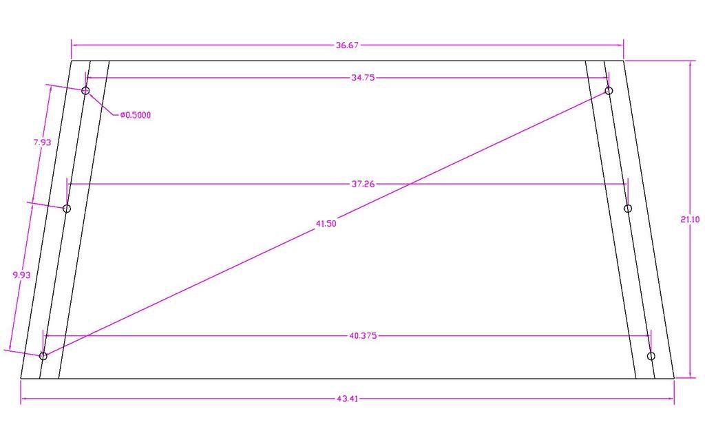
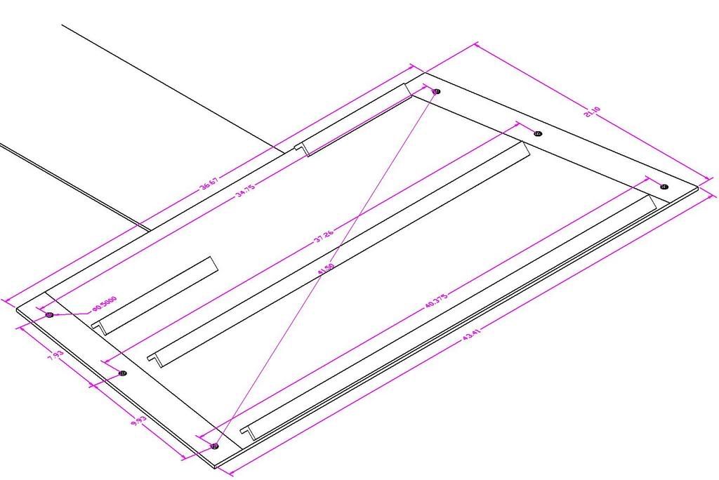
After installing the Body lift and Motor mount lift I jacked up the transmission, removed the stock skid and measured the holes. This was much easier than my previous attempts to measure with the skid in place. A little time on Auto CAD and I came up with this.
![Image]()
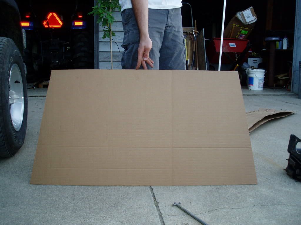
I plotted a full scale drawing and made a template to test fit it.
![Image]()
Next step was ordering a 24" X 48" X ¼" steel plate from a local metal fabricator. I then used my drawing and marked it on the plate. Fortunately I was able to sheer it at work and save about 25 cut off wheels and 3 hours of grinding. Using the template I drew as well as the stock skid for a reference I marked and drilled six ½" holes to mount the skid to the frame.
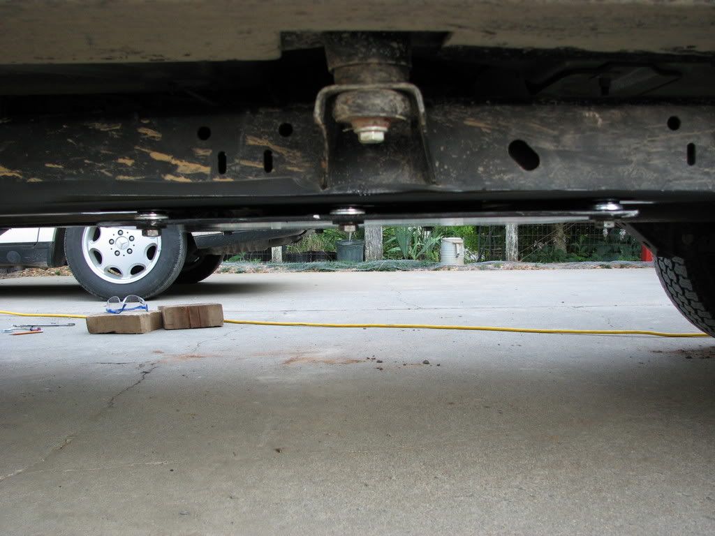
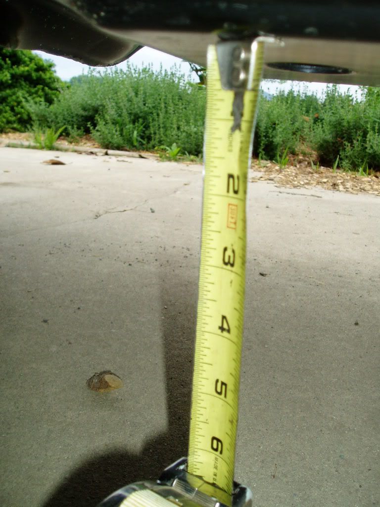
I had already measured my stock clearance at 9.75"
![Image]()
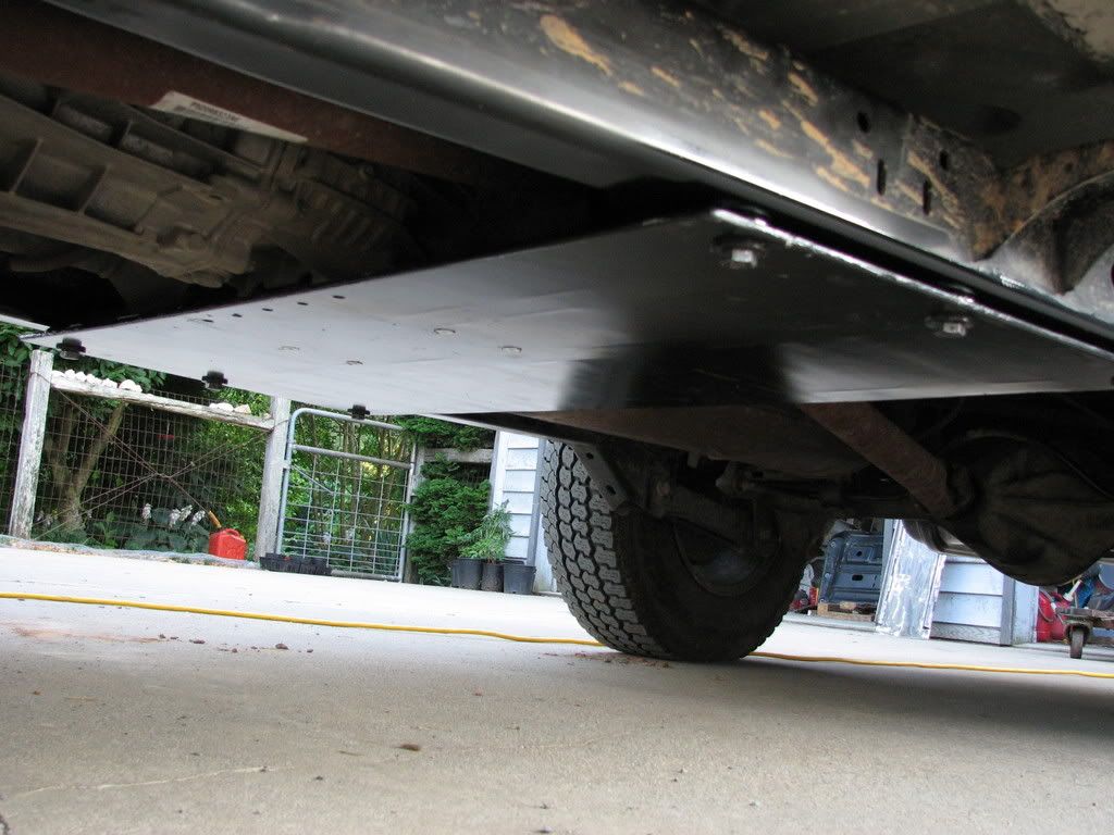
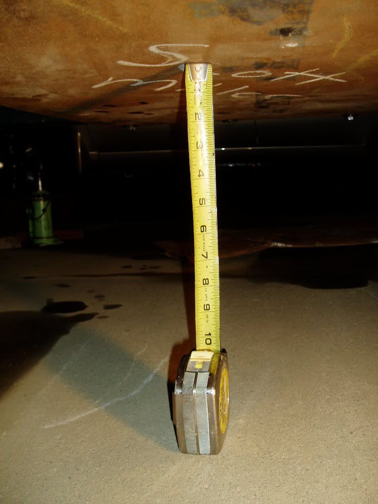
I mounted the new skid and measured my new clearance at 13.75".
![Image]()
Gain in clearance 4" SWEET!! :woot:
I traced the 33 Engineering trany mount and drilled the holes. Bolted the skid on and got ready for a test drive.
Now when you do a body lift and motor mount lift they say to check fan to make sure its not making contact with the shroud. I did it then, but after raising the drive train it was contacting it pretty bad, found that out pretty fast too:laugh:. It was late and the bars were open so no test drive that night. The next day I drilled new holes in the shroud and re mounted it to center the fan in the shroud. WHEW! That was easy…. NOT! That fan shroud is a pain to work on and I only got the upper 2 bolts in it. It is staying like that until future work is required or I come up with a right angle drill. So a test drive showed everything working great took it up to 50 on the back roads no vibes other than my exhaust pipe contacting my trailer hitch. 5 minuets with a grinder fixed that. I took off about 3/8" off the tip. Well I drove to work like this and discovered that under heavy acceleration from around 47-53 mph I had a drive line vibration. Fixed that by dropping the skid with 3 washers and only needed 2 when the final installation came around. Another problem was part of the transfer case was contacting the skid. I had already determined the transfer case mount was not level with the frame rails and fixed this by adding 2 washers between the drive's side of the mount and the skid plate.
UPDATE EDIT: After wheeling I found while torquing the engine in reverse my TC was still hitting my skid. Today I made a 1/4" spacer plate to replace the washers and provide a little more lift. No further problems.
Just to note my Transfer Case linkage was way out of whack after the BMML and BL. After putting on the Flat TC skid it all works again, needs to be adjusted but should be fine. I might add a shifter linkage relocation bracket if I can't get it adjusted properly.
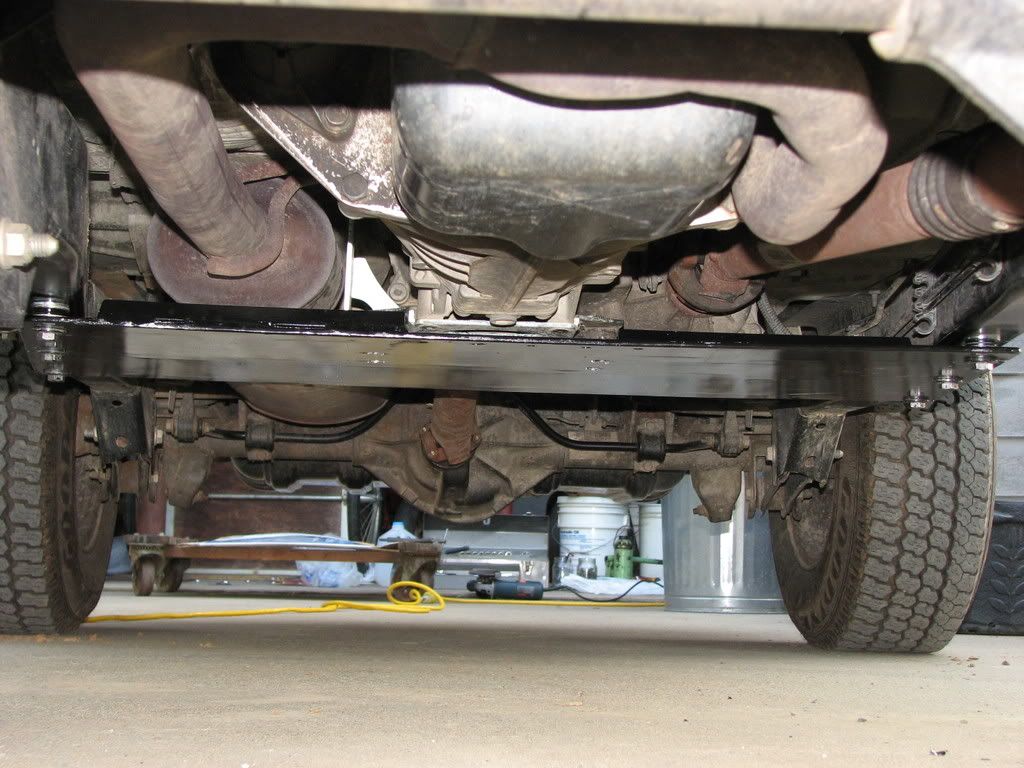
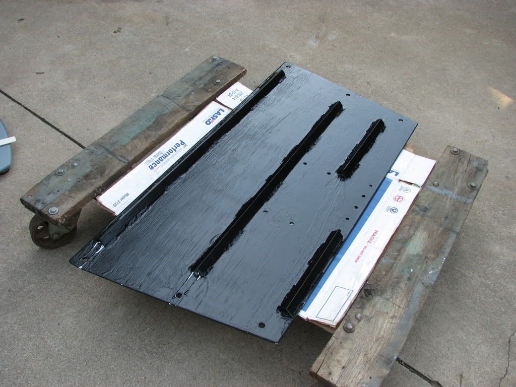
My skid plate was also bowing slightly. Once again consulting Jeep Forum I decided to brace it with 1 X 1 X ¼" angle. Picked up 20 feet and a 12" X 40" X ¼" plate from a different local welding place. That plate is for the Engine skid.
Here is where the final bracing was located.
![Image]()
You can see at the front where the engine skid will be going, but that's a later write up.
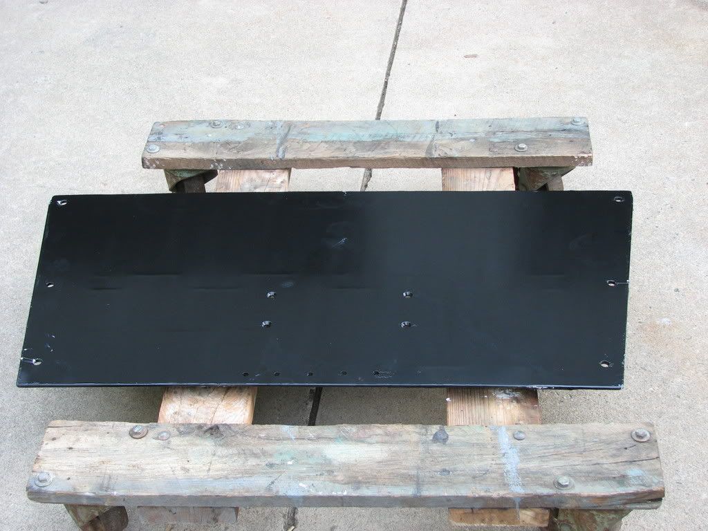
After welding on the bracing, sanding, grinding, and cleaning I primed and painted the skid. Fortunately the can of brush on primer was kicked over and I only had enough to do the topside of the skid. I say fortunately because it looked like ***, I should have just used spray primer on the whole thing.
And here it is painted.
Bottoms up
![Image]()
*** side
![Image]()
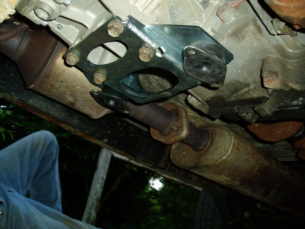
The 5 holes in the front are where I am bolting on my engine skid. The 4 holes in the middle are where the Transmission mount bolts on. I did not include these in the drawing because they will change a lot more than the other dimensions for other Jeeps.
Extensive researching and Jeep Forum searching led me to the following information.
Most people who do a high clearance TC skid are already lifted. In this case you need the following to raise your drive line higher if you do not already have it.
SYE+CV drive shaft
Adjustable rear control arms
Body lift
Motor lift
High Clearance TC skid of your choice.
TC shifter relocation bracket
Being at stock height I felt I did not need the SYE+CV drive shaft or Adjustable rear control arms. I felt this way because I have an Unlimited and usually people can do a Budget boost or even a 3.5" lift with out needing these, and with no to minimal TC skid drop. I did need the following.
Body lift (JKS 1.25" BL)
Motor mount lift (Home Made)
33 Engineering Transmission Mount (1.5" lower profile over stock Trany mount)
Steel to make the skid.
Assorted bolts nuts and washers.
Drive train to tub, clearance:
Body lift +1.25"
33 Engineering Transmission mount +1.5"
Total gain in clearance 2.75", this combined with the clearance of the stock jeep let me raise the drive train around 4"
My rear drive shaft angle was also a concern I felt I could raise the Transfer case 3" without having a SYE and CV Drive shaft. That is why I needed the 33 Engineering transmission mount. The fact I had also incorporated a motor mount lift messed up this thought process a little. Because I was lifting the TC more than the motor this increased my drive shaft angle more than my calculations led me to believe.
After installing the Body lift and Motor mount lift I jacked up the transmission, removed the stock skid and measured the holes. This was much easier than my previous attempts to measure with the skid in place. A little time on Auto CAD and I came up with this.
I plotted a full scale drawing and made a template to test fit it.
Next step was ordering a 24" X 48" X ¼" steel plate from a local metal fabricator. I then used my drawing and marked it on the plate. Fortunately I was able to sheer it at work and save about 25 cut off wheels and 3 hours of grinding. Using the template I drew as well as the stock skid for a reference I marked and drilled six ½" holes to mount the skid to the frame.
I had already measured my stock clearance at 9.75"
I mounted the new skid and measured my new clearance at 13.75".
Gain in clearance 4" SWEET!! :woot:
I traced the 33 Engineering trany mount and drilled the holes. Bolted the skid on and got ready for a test drive.
Now when you do a body lift and motor mount lift they say to check fan to make sure its not making contact with the shroud. I did it then, but after raising the drive train it was contacting it pretty bad, found that out pretty fast too:laugh:. It was late and the bars were open so no test drive that night. The next day I drilled new holes in the shroud and re mounted it to center the fan in the shroud. WHEW! That was easy…. NOT! That fan shroud is a pain to work on and I only got the upper 2 bolts in it. It is staying like that until future work is required or I come up with a right angle drill. So a test drive showed everything working great took it up to 50 on the back roads no vibes other than my exhaust pipe contacting my trailer hitch. 5 minuets with a grinder fixed that. I took off about 3/8" off the tip. Well I drove to work like this and discovered that under heavy acceleration from around 47-53 mph I had a drive line vibration. Fixed that by dropping the skid with 3 washers and only needed 2 when the final installation came around. Another problem was part of the transfer case was contacting the skid. I had already determined the transfer case mount was not level with the frame rails and fixed this by adding 2 washers between the drive's side of the mount and the skid plate.
UPDATE EDIT: After wheeling I found while torquing the engine in reverse my TC was still hitting my skid. Today I made a 1/4" spacer plate to replace the washers and provide a little more lift. No further problems.
Just to note my Transfer Case linkage was way out of whack after the BMML and BL. After putting on the Flat TC skid it all works again, needs to be adjusted but should be fine. I might add a shifter linkage relocation bracket if I can't get it adjusted properly.
My skid plate was also bowing slightly. Once again consulting Jeep Forum I decided to brace it with 1 X 1 X ¼" angle. Picked up 20 feet and a 12" X 40" X ¼" plate from a different local welding place. That plate is for the Engine skid.
Here is where the final bracing was located.
You can see at the front where the engine skid will be going, but that's a later write up.
After welding on the bracing, sanding, grinding, and cleaning I primed and painted the skid. Fortunately the can of brush on primer was kicked over and I only had enough to do the topside of the skid. I say fortunately because it looked like ***, I should have just used spray primer on the whole thing.
And here it is painted.
Bottoms up
*** side
The 5 holes in the front are where I am bolting on my engine skid. The 4 holes in the middle are where the Transmission mount bolts on. I did not include these in the drawing because they will change a lot more than the other dimensions for other Jeeps.
 ). :2thumbsup: